Strategic oil analysis: Lubricant sampling for quality results
Mike Johnson & Matt Spurlock | TLT Best Practices December 2009
A good program is greatly influenced by the sample-collection process.

www.canstockphoto.com
KEY CONCEPTS
•
Oil samples should maximize sump and machine condition indicators and minimize background interference.
•
The sample process should be perfectly repeatable.
•
Repeatability depends on the use of fixed sample ports.
This is the last article of TLT’s five-part series, which is intended to introduce and discuss key principles and parameters that determine oil analysis effectiveness.
In previous articles we’ve suggested that oil analysis is the feedback loop that tells the practitioner whether the lubrication activities are delivering the expected results from the lubrication program. Oil analysis plans should be designed to provide information about the state of the lubricant condition, the cleanliness of the sump and the condition of the machine. Additionally, we’ve reviewed test types and organization of tests into a test slate for each of several machine types. Lastly, we’ve reviewed predefined alarm sets designed to create an alarm state anytime the actual data exceeds the alarm limit.
Each of these topics warrants thorough consideration by the reliability engineer or machine lubrication practitioner before initiating a site-specific analysis program. This article addresses the highly important topic of sample collection.
SAMPLE COLLECTION QUALITY
Realizing that each of the previously mentioned topics should be fully understood prior to launching a program, there is nothing that can cripple a well-designed program as quickly as poorly devised sampling practices. This axiom applies to any type of quality measurement program based on sampling and analysis.
Sample collection quality is dependent on three key parameters:
•
Timeliness
•
Accuracy in representation of actual machine and sump conditions
•
Repeatability.
A misstep in any of these areas can produce seriously misleading impressions of the health of the machine/tribosystem and potentially damaging decisions to either act or refrain from action.
TIMELINESS
Experience suggests that analysis program managers conduct sampling activities on intervals ranging from weekly (for in-house screening) to annually. Programs devised around weekly and other short interval collections tend to have well-developed missions and are sampling at short intervals for those machines that are subject to tremendous environmental challenges.
Food-processing plants that have mandated daily wash-down requirements, particularly those facilities handling meat products, are good candidates for weekly in-house screening in response to the high risk for wash-water contamination of machine sumps. Though machine designers and reliability engineers place emphasis on sealing configurations and prevention of contamination, sumps routinely become emulsified with caustic wash-water. Short sampling intervals help to catch these conditions as they occur. These programs tend to place greater emphasis on the in-house test results and use this information to drive the laboratory-based sampling activities.
It is common for organizations to sample machines at longer intervals in order to control expenses. If there isn’t a well-developed plan for how to use the data to improve machine availability, this seems rational. Sampling at intervals between six months and one year is common in the absence of a true management strategy.
Often the impetus for analysis is provided by the lubricant supplier through an offer of free analysis conducted at three- to 12-month intervals depending on several factors. This plan for testing is useful to eliminate unnecessary oil changes, particularly for large-capacity sumps, if the data indicates stable oil health and minimal evidence of wear. However, evidence of wear sometimes drives oil changes, which only serves to hide an underlying problem. Additionally, it is not unusual for the free analysis offering to neglect costly contamination control test methods that could provide additional highly useful insight into machine and sump conditions.
There is no question that some value can be derived from testing to check oil health, but the value is low relative to that provided by a machine health-centered approach. Sample frequencies should be driven by a few key considerations, including:
•
Machine importance.
•
Oil type, characterized by mineral oil or synthetic-based product.
•
Oil age.
•
Dynamic machine stress, characterized by high-speed, high loads and shock loads.
•
Operating environment stress (heat, moisture, solid debris, process contaminants).
Table 1 offers proposed starting intervals for machines and test types based on combined machine importance to production, operating modes and types of sump configurations (static, dynamic, pressurized).
Table 1. General Considerations for Oil Sampling Frequencies Based on Test Type, Machine Criticality and Operating State.
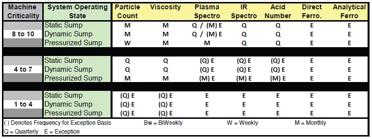
As was noted in previous articles, a static sump is one where the oil resides in and moves around the housing based on the movement of components. A dynamic sump is one where the oil drains from the working component housings to a secondary tank where a pump circulates the oil back to the components, typically at low pressures (> 100 PSI). A pressurized sump is one where the oil circulates through the machine and components under much higher system pressures. Hydraulic systems are considered pressurized sumps.
As shown in Table 1, if multiple tests are to be run for a given machine, the interval should reflect the shortest time cycle noted for the test slate. Alternately, one may commission the lab to conduct only the tests that are due based on actual history. After arriving at a satisfactory starting point, the program manager may choose to increase or decrease intervals based on other stresses, as shown in Table 2.
Table 2. Interval Factors Driven by Operating and Environmental Considerations.
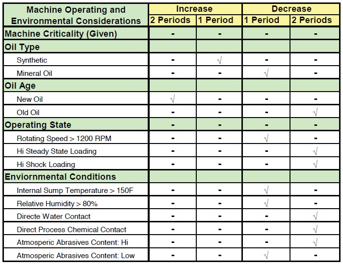
The final interval selection should reflect awareness for the potential for change in machine condition, sump condition (contamination load) and lubricant health between samples. The more the sump is subject to rapid change, the shorter the analysis interval should be.
MACHINE AND SUMP CONDITIONS
Machine and sump conditions may differ appreciably from one end of the sump to the other. There can be distinct layers of oil movement within the sump with the layers blurring into a uniform condition as the proximity to the mechanical components closes.
Samples collected from the top and center of the circulating system show much less real-time machine and contaminant information than the sample collected from the return line before the oil hits the reservoir. Reservoir design greatly influences how quickly and where the evidence of machine condition and contaminant loading falls out of the oil.
Figure 1 depicts the nature of oil movement within a simple multistage reducer. The oil layers closest to the moving components have the complete composition of the wear and contaminant concentration, and the composition changes as the gap between the components and the floor and sidewalls increases. The reasoning is simple: warm oil allows high-density contaminants (atmospheric and wear metal) and moisture to settle quickly. As the gap between the component and sump bottom increases, the oil becomes progressively more stagnant, which allows for settling to occur. Wear debris, solids and moisture accumulates at the low points in the reservoir. Samples collected from these low points (i.e., drain ports) carries a disproportionally high amount of material that represents historical conditions.
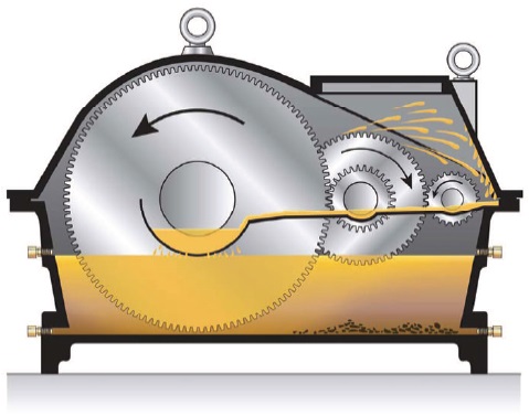 Figure 1. Sump conditions vary inside each machine.
The point from which the sample is extracted should be as close as possible to the load zone of the moving components. This area most effectively reflects the wear state of those moving components. Additionally, oil collected from these regions carries less historical information than the stagnant oil near the sides and bottoms and reservoir drains.
SAMPLE REPEATABILITY
Once the location for most representative sample location has been selected, the remaining challenge is to retrofit the sump to enable extraction from this location with the least possible chance for influence from the sample process itself and/or from the immediate surroundings and with the greatest possible chance of exact duplication.
Sample repeatability is crucial for any type of machine condition monitoring technique. Without repeatability in collection, any change in machine wear or contaminant load datum from the previous sample begs the question of cause. Since these aspects of the analysis plan are not homogenous (uniform from one end of the sump to the other), any variability from the collection process itself causes a misrepresentation of the actual state. When variability occurs, management must try to make intelligent comparisons between the previous and current machine states without knowing which state was accurate.
Some benefit can be derived from highly variable sampling activities. The homogenous properties (viscosity, chemical degradation, additive degradation) may still be effectively evaluated because the properties are not dependent on the location of extraction. However, higher value information about machine health and contaminant levels is lost.
FITTING SELECTION AND PLACEMENT
Periodically engineers and managers encounter forks in the long, arduous road to quality practices. This is one of those forks. Following the themes noted above, the only way sample collection can be conducted in such a way that the extracted sample is always highly representative and repeatable is for the practitioner to proceed with a fixed sample port installation.
Even surrendering the argument that sometimes the fixed sample port will be installed in a location that is not perfectly representative—for whatever sample quality can be obtained—it isn’t possible for sample collection to be done repeatably without removing all possible sources of variability. If management wants to use lubricant-based data to support effective decisions, fixed sample ports have to be installed and used to eliminate questions about the usefulness of the collected sample.
A sample port, or sample fitting, is a device that is permanently installed onto the machine through which the oil will flow into the collection bottle. There are reasons to have both primary and secondary fittings. The primary fitting represents the general state of the machine as a whole to the extent that the port location is capable of providing this information. Secondary ports are used to troubleshoot for and identify specific issues that have been uncovered during routine primary sampling and analysis activity. There can be multiple secondary sample fittings for a machine or assembly of machines. In fact, this is common for sophisticated hydraulic and circulation systems.
Each possible secondary port represents information about a particular branch or working region of the system. For instance, if the routine analysis indicates that the solid contaminant level has increased in the whole of the system, collecting an additional sample from both upstream and downstream of the filter element can enable the practitioner to decide whether or not the filter element is the culprit.
The sample fitting should be selected based on the best fit for the machine’s location, regardless of whether it is a primary or secondary port. There are several types of fittings, and most machines have a variety of spots where the fittings can be installed. Figures 2, 3 and 4 show commonly available fittings. Each is equipped for threaded insertion into an existing component housing port.
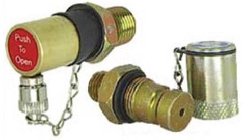 Figure 2. Push button (shown on the left) and needle-probe type sample ports for low but positive pressure installations. (Courtesy of Condition Monitoring International)
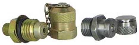
Figure 3. Gauge plug (shown on the left) and flush mount type sample ports for static (gravity flow) and pressurized system sample collection. (Courtesy of Condition Monitoring International)
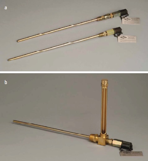
Figure 4. (a) Pitot tube and (b) level gauge-equipped pitot tube for static and pressurized sample collection. (Courtesy of TRICO Corp.)
If the correct sample port location doesn’t have a threaded port, then a simple modification via drill and tap for a threaded port is required. The prospect of drilling and tapping the machine housing gives most reliability and maintenance managers a good reason to pause and carefully reflect on whether this is the right location and approach or whether an adequate alternative is available.
Using the gear drive illustration from earlier in this article, Figure 5 shows how the pitot tube type sample port could be manipulated for placement at an ideal location to capture evidence of incipient wear from the likely location of early wear—the area around the mesh of the low-speed final reduction gearset.
 Figure 5. Pitot tube sample port properly fitted for a gear reducer.
It was previously noted that the hydraulic or circulating system primary samples should be taken from the return line before the reservoir, but there are instances where it isn’t possible or at least isn’t possible without a major engineering redesign and rebuild. In those instances, reservoir sampling must be done with a clear focus on capturing working and purposefully avoiding stagnant oil.
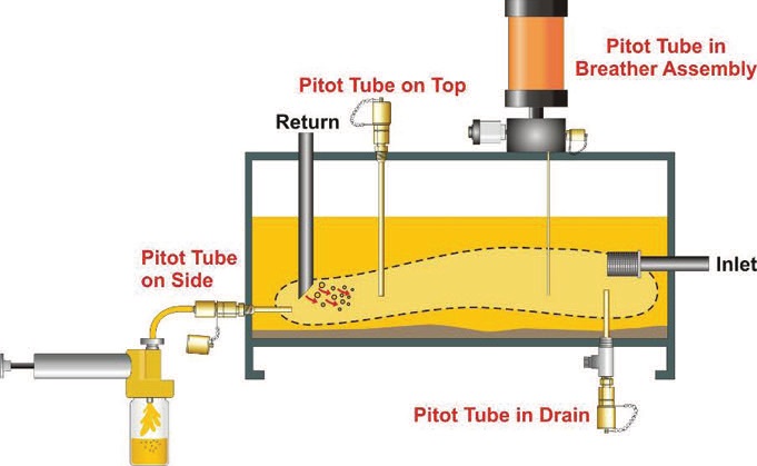 Figure 6. Typical locations for the installation of pitot tube type collection ttings. (Courtesy of TRICO Corp.)
After setting the sample ports, the next area for potential variability exists in the sample collection activity itself. The risk can be greatly minimized by creating and exercising clearly written sample collection procedures for each unique fitting configuration. Sample collection tubing and bottle cleanliness should be figured into the collection procedure.
CONCLUSION
The quality of the oil analysis program is dramatically influenced by the collection process. Fixed sample ports must be used, whatever their capacity for representative feedback, to avoid variability in the sample process. The effectiveness of lubricant-based management decisions hinges on the quality of the sample.
 Mike Johnson, CLS, CMRP, MLT, is the principal consultant for Advanced Machine Reliability Resources, in Franklin, Tenn. You can reach him at mike.johnson@precisionlubrication.com
.
 Matt Spurlock, CMRP, MLA II, MLT I, LLA I, is the machine lubricant subject matter expert at Allied Reliability, Inc., in Indianapolis, Ind. You reach him at spurlockm@alliedreliability.com
.