Strategic oil analysis: Developing the test slates
Mike Johnson & Matt Spurlock | TLT Best Practices July 2009
Following these methods will help generate data that represents actionable knowledge about the sampled machine.

www.canstockphoto.com
KEY CONCEPTS
•
Two key factors that influence test slate design include machine maintenance strategy and machine failure modes.
•
Test slates should be designed to quickly and accurately identify the initial signs of the common failure modes for the given machine components and operating states.
•
Machine owners should accept responsibility for defining the test methods, secondary methods and alarm limits for their programs. Owners must also provide the lab with a full accounting of lubricant brand, type, grade and lubricant operating hours in order for the lab to provide an accurate measurement.
Lubricant-based machine condition analysis has become one of several mainstream technologies used by reliability engineers and machine owners in their efforts to improve machine performance. It took many years for the quality of the end product—a machine condition assessment—to achieve broad-based respect.
The end product—the machine condition report—has improved for many reasons. Certainly, developments in instrumentation have enabled service providers to improve the consistency and quality of each analysis technique. These same improvements also have enabled service providers to conduct tests more efficiently, quickly and cost-effectively.
With the integration of computers and the development of programs that enable management of incomprehensibly large amounts of data, quality and cost improvements have greatly benefited both lab and machine owners. Recently, Web-based programs have started to push quality and performance capabilities even more through the integration of improvements in instrumentation, pure computational power and information/communication sciences, enabling the nearly instantaneous delivery of information following the lab-based analysis event itself.
The conductors leading this symphony of technological development and continuous improvement are the many instrumentation designers, reliability and lubrication engineers and their staffs that are pushing the boundaries of expectation for this science to deliver actionable commentary on each and every specific machine. The delivery of actionable commentary on each and every machine represents the biggest challenge that oil analysis service providers have yet faced.
Simply providing high quality, consistent, instantaneous data about the sample is no longer enough. The data must now be delivered in a form that represents real, actionable knowledge about the sampled machine. To accomplish this purpose, the service provider now must also become an expert at analyzing machines within a specific operating context and understand the differences between machines for their different operating contexts. This is a difficult proposition unless the service provider has full knowledge of machine design and operating context and is able to use extensive analysis of historical data to render a more exacting opinion from current datum. One necessary step to take with this rise in expectation is the replacement of generic oil analysis test slates with machine-specific test slates and alarm sets.
In May we introduced the most common oil analysis test methods and provided a basic description of each. In Part III of this five-part series, we will introduce machine-specific test slates for five common machine types.
PROACTIVE VS. PREDICTIVE
It is not uncommon for a service provider to have oil analysis test slates broken up into either basic or comprehensive test groups. These are not appropriate for today’s maintenance challenges. While elemental analysis and viscosity measurement remain the cornerstones in most test suites, relying solely on these two tests no longer achieves the required results.
Two key factors that influence test slate design include machine maintenance strategy and machine failure modes. Successful proactive and predictive maintenance initiatives are dependent on labs and practitioners delivering appropriately designed and executed analysis, and rendering accurate and actionable results.
The proactive maintenance strategy seeks to achieve machine lifecycle extension through the elimination of root causes of potential failure. A properly designed analysis plan can deliver very strong support of a proactive strategy if the results are taken seriously and acted upon.
Predictive maintenance strategy seeks to support management of machine maintenance following development of an incipient failure. This plan uses analysis to identify a failure condition and to monitor that failure accordingly in an attempt to time the required maintenance action such that maximum life can be derived from the component for the given conditions.
Either maintenance strategy is sure to save the owner plenty of money in the long run vs. simply running the machines to failure. However, a combination of these strategies results in the highest ROI for the oil analysis program. Recognizing the strategy behind the analysis effort allows the user to make more informed decisions regarding oil analysis test slates.
One must also understand the potential failure modes for the components being tested. For this process, a facility may find it beneficial to go through a Failure Modes and Effects Analysis (FMEA) exercise. Let’s look at the common failure modes for each of the component types listed above and the appropriate tests to address that specific failure mode.
Following are a few common modes and the best test methods for identifying those modes.
COMMON MACHINE FAILURE MODES
Fatigue, two-body and three-body abrasive wear. Generally this involves very small particles detected through elemental analysis as a primary test, with particle counting as a supporting/confirming test. Components susceptible to this mode include gears, element bearings, low speed and small-surface area plain bearings, hydraulic vane and piston pumps, pumps, various combustion engine components, reciprocating compressor cranks and cylinder rider bands.
Severe sliding and severe fatigue wear. Severe wear can be divided into several categories. Fortunately, the detection methods are similar depending on the metallurgy of the component being monitored. A severe wear mode produces large debris particle sizes, much of which cannot be detected via elemental analysis. Therefore, additional tests should be included in the slate to catch this failure mode.
Though typically used to measure atmospheric contamination, particle counting can be a leading indicator of a severe wear problem. Large particle (>14 microns) monitoring quickly reveals an onset of aggressive wear. When using particle counting for this purpose, it is important that the end-user monitor the raw particle count data rather than the ISO cleanliness code.
In industrial gearbox and pump applications, where gears and element bearings are the primary wearing subcomponents, ferrous density analysis should also be part of a standard test slate. Ferrous density measurement can be conducted from either direct read ferrography or particle quantifier methods.
Components susceptible to a severe wear mode include gears, large intermediate to high nDm element bearings with little preload (smearing conditions), high unit load and low-speed plain bearings, hydraulic vane and piston pumps and engine components.
Environmental contamination. Dirt or process debris detection depends primarily on particle counting and secondarily on elemental analysis, which helps to determine the atomic makeup of the debris (i.e., silicon/aluminum are indicators of dirt, sodium can be an indicator of salt). Awareness/knowledge of potential contaminants is a key for proper diagnosis. Moisture is detected generally with a screening test such as hot plate or FTIR, with confirmation performed through Karl Fischer testing. Care must be taken at the laboratory to select an appropriate method since some additives can adversely affect the Karl Fischer results.
All machine components are susceptible to environmental degradation and the consequential wear mechanisms.
Fluid degradation. Increased acid number combined with an increase in FTIR oxidation/nitration/sulfation value is a strong indicator of fluid degradation. Both of these conditions result in an increase in the viscosity of the lubricant. An increase showing in all three tests is a sure indication of fluid degradation. It should be noted that an increase in any single parameter for fluid properties may not be justification for fluid condemnation.
Contaminant loading, namely wear debris, moisture and heat, are directly responsible for increases in fluid degradation that can lead to varnish and sludge formation that may produce one or more of several varnish types. Varnish formation on contact surfaces accelerates wear by limiting lubricity improver agents (AW/EP/compounding) access to the mechanical contact area, eventually degrading wear resistance and promoting an increase in wear rates.
Following the Arrhenius rate rule in organic chemistry, the rate of lubricant degradation is expected to double with each 10 C increase in sump temperature. Cooling machine sumps increases lubricant lifecycles. Adding to this threat, Figure 1 (
1) shows the impact that increased contamination can have on the lubricant’s basestock. Once oxidation inhibitors are depleted, oxidation rates escalate rapidly.
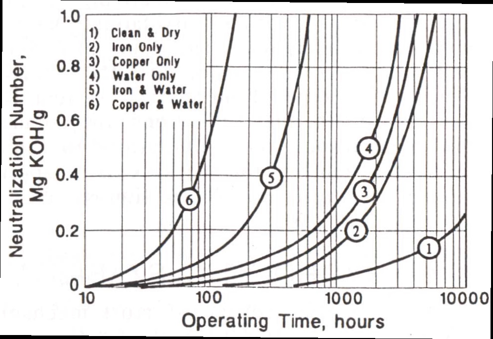 Figure 1. Oxidation rates increase dramatically with increases in moisture, iron and copper, and with these in combination.
All machine sumps are susceptible to lubricant degradation. However, those sumps operating with temperatures at or above the operator’s pain threshold for a five-second period of direct surface contact are prime candidates for lubricant degradation. In absolute terms, any sump with oil temperatures at or above 70 C/158 F is a strong candidate for rapid lubricant degradation.
Incorrect lubricant. An incorrect lubricant is just what it sounds like and is, fortunately, easy to identify. An incorrect lubricant can be identified through the use of viscosity, elemental analysis, FTIR oxidation and neutralization number. In addition, a full FTIR spectrum comparison of additive types against the spectrum of the new oil can be used to identify lubricant mixtures and incorrect applications.
All machine sumps are susceptible to cross contamination. It should be noted that cross contamination also can occur during shipping and handling before the lubricant reaches the plant site and that periodic statistical sampling of incoming lubricants should be conducted to verify chemical, viscometric and cleanliness qualities.
MACHINE-SPECIFIC TEST SLATES
While component types can vary widely, this article addresses some of the most common component types, including:
1.
Industrial gearboxes, both sliding (worm) and non-sliding (spur and helical) designs
2.
Hydraulic systems
3.
Turbine generators
4.
Pumps
5.
Compressors.
Figure 2 provides an overview of both primary and secondary tests for these machine types in keeping with the theme of reliability for stationary production machines. Specific test methods for each, where applicable, are noted. Alarm types also are noted, with additional details to follow in the next article in this series.
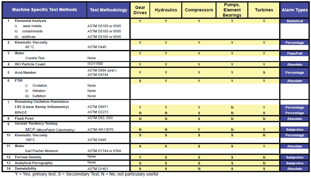 Figure 2. Recommended test methods for common machine types.
Engines are obviously the most common machine type. Engines have been and will continue to be thoroughly addressed by others involved in the field of machinery lubrication, but combustion engine considerations are not included in this series of articles. Test purpose, method and function for most of these tests were introduced in Part II.
 An incorrect lubricant can be identified through the use of viscosity, elemental analysis, FTIR oxidation and neutralization number.
SUMMARY
An incorrect lubricant can be identified through the use of viscosity, elemental analysis, FTIR oxidation and neutralization number.
SUMMARY
As lubricant-based machine diagnostic methods improve, the selection of tests slates has shifted from generic to highly specific. The test slate for any given machine should follow the machine owner’s strategy and plan for how to use the information (proactive or predictive mode) and should include test methods that effectively measure for the common failure modes for the machine under consideration.
Machine owners and reliability engineers should work directly with their service labs to design test slates that include appropriate primary and secondary tests. The commercial agreement should include an understanding that once predefined alarm values are surpassed for the primary tests, then the secondary tests automatically are conducted and the results quickly reported to the machine owner.
REFERENCE
1.
Fitch, E.C.,
Proactive Maintenance for Mechanical Systems, p. 102, FES, Stillwater, Okla.
 Mike Johnson, CLS, CMRP, MLT, is the principal consultant for Advanced Machine Reliability Resources, in Franklin, Tenn. You can reach him at mike.johnson@precisionlubrication.com
.
 Matt Spurlock, CMRP, MLA II, MLT I, LLA I, is the machine lubricant subject matter expert at Allied Reliability, Inc., in Indianapolis, Ind. You reach him at spurlockm@alliedreliability.com
.