Lubricant management: Dynamic circulating systems
Mike Johnson, Contributing Editor | Best Practices June 2009
Sump condition control must be a key element to any lubricant management strategy.
KEY CONCEPTS
•
Lubricant management is the set of practices that protects the lubricant and machine surfaces from degradation and dictate the long-term success of mechanical reliability.
•
With static sumps, the oil stays with the component. With dynamic sumps, oil flows to a component, does its job and returns to a reservoir until the process is repeated.
•
Moisture, heat, particulates and even the air itself are contaminants that can be harmful to the lubricant and eventually the machine.
Lubricant management could mean different things to different people within a facility. The shipping and receiving clerk might view this as a part of inventory control. The maintenance planner or lube crew supervisor may view lubricant management as the process that assures that machines scheduled for level checks, replenishment and oil changes are serviced in a timely manner. The condition monitoring technician may think sample collection for analysis and long-term planning. Each could be correct, but the intent for this article is to address yet another aspect of the interesting world of reliability centered lubrication: sump condition control.
IN REVIEW
There are three distinct aspects of a reliability centric machine lubrication plan.
First, each machine must be evaluated for and receive the viscosity grade which assures that a full hydrodynamic (for sliding contacts) and elastohydrodynamic (for rolling contacts) film can be developed to separate operating machine components. Lubricant grade (ISO viscosity grade for oil and grease) decisions must follow a careful and thoughtful evaluation of all machine components and their interactions, leading to highly objective decisions.
Second, each product/brand selection decision must be made with full consideration of each machine operating context (heat, load, speed, environment, accessibility, etc.) to assure the lubricant performance capabilities effectively match the operating demands. This part is less objective.
There are clear differences in lubricant performance capabilities that can be seen in both bench top and field testing results. High performance products can be derived from both synthetic and mineral oil-based chemistries. Performance differences follow differences in quality of base oil and additive raw materials selections and from differences in the engineering of protective film formulations. It is inevitable that differences of opinion between suppliers about their respective lubricant performance properties will arise. A healthy debate over performance measurement is good for the task of finding the best fit and should not be avoided (as long as a decision is finally reached).
Assuming the correct viscosity grade and performance criteria decisions have been made, lubricant management represents the set of practices that protects the lubricant and machine surfaces from unrelenting degradation and that dictate the long-term success of machine mechanical reliability.
The third aspect is arguably the most technically and managerially taxing. It is the collection of choices and decisions (tactics) that determine the interdependent influences of long-term lubricant health and sump cleanliness control. These tactics should follow the reliability strategy set forth by senior management.
The January 2008 TLT article that started this series of Best Practice articles provides an overview of the importance of the reliability strategy and suggests tactics for prioritizing machines by degree of importance. A review of that article may be useful before proceeding with this article. This article will differentiate between dynamic and static sumps but focus on dynamic sumps. It identifies the common culprits that lead to lost condition control and offers suggestions for improvements.
DYNAMIC VS. STATIC SUMPS
Strictly speaking any assembly of moving machine parts protected by a lubricant bath is dynamic. For our purposes, however, we will differentiate between dynamic and static based on whether the lubricant stays with the components or not. An automobile differential is a static sump. The oil stays in the housing with the gears. An automobile engine is a dynamic sump. The oil does some work, drains from the components into a reservoir, is captured and returned to the components, where the process is repeated.
Static sumps for industrial machines tend to be simple enclosures surrounding moving components. Equipment owners typically do not specify standards for seals, filters, heat limits, moisture control, sump volumes or sample/filter port dimension and location. Consequently, machine sumps for ‘simple’ assemblies, such as gear drives and bearing enclosures, tend to be open to the environment.
Dynamic sumps depend on the use of a pump to move the oil. The pump may be integral to the machine, such as a pump installed on a gear shaft in a multireduction drive, or may operate independently of the machine. Machines with complex design or operational parameters (very high or low speeds, high loads, high temperatures, environmental extremes, etc.) tend to incorporate forced circulation and supply.
Given these common patterns, there are many industrial sites where the highest criticality-rated machine operates with a simple static sump.
CONTROLLING COMPONENT DEGRADATION
There is a large body of research suggesting that common wear problems are associated with overall lubricant condition and cleanliness. Common experience supports these positions when one stops to consider the facts. Oil- and grease-lubricated machines and components that operate with continuous environmental challenges (paper mills have process chemicals, cement mills have process abrasives, steel mills have both) without the benefit of lubricant and sump cleanliness controls experience short life cycles and exaggerated repair costs.
Bearing manufacturers have, to their credit, advertised failure causes for bearings and encouraged their customers to focus on removing the underlying causes. Figure 1 illustrates this well.
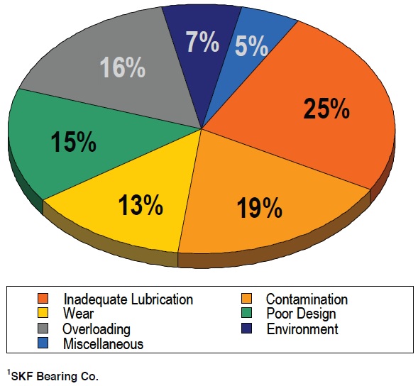 Figure 1. Common contributors to bearing degradation (1).
Inadequate lubrication includes: the wrong viscosity, the wrong additive types, degraded lubricant health, too little or too much lubricant, too frequent or too infrequent reapplication. The contamination challenges are obvious and ubiquitous: moisture, air, heat, machine wear debris and particulate from the plant atmosphere.
Coincidentally, these two categories of problems are self-perpetuating. Increases in contaminant loads lead to increases in wear debris, which accelerates the oxidation cycle, which weakens the lubricant, which can contribute directly to more wear debris, perpetuating the cycle.
Contamination control may be the single largest area for improvements from the implementation of precision lubrication practices.
CONTAMINANTS REVIEWED
Industrial sites are ripe with contamination sources. The most common problems are in the air we breathe: moisture, particulate, heat and the air itself.
Moisture. Water contamination is the fuel that propels oil and machine destruction. Moisture accelerates wear through corrosion from direct contact with surfaces, corrosion from Chemical changes in the oil (particularly for AW and EP oils) and by increasing the risk of film collapse under load. Condensation (water drops) can form on the underside of tank lids, create rust and elevate solid contaminant loads as well. Moisture also promotes vaporous cavitation and destruction of pump surfaces.
Particulate. There is overwhelming evidence that suggests solid contaminants in oil causes wear. There are clearly defined methods for evaluating concentrations of solids at predefined sizes and for measuring the (chemical) composition of the solids. There is no doubt that mechanically astute people universally believe that particulate in the oil is harmful.
Particles promote micropitting, fatigue and three-body wear in proportion to their concentration in the oil. Higher particle counts mean higher wear rates—and this pertains to all types of lubricated components. As wear increases, the catalytic effect of iron and copper debris accelerates chemical reactions and increases the rate of aging.
Air. The very air we breathe is a poison to the lubricant. Air provides oxygen, the other fuel, which promotes chemical reactions and drives the aging process. About 10% of the volume of a container of mineral oil is dissolved air. This is a natural state and tolerated in formulation decisions, but air in higher percentages is problematic.
Air entrainment, or air saturation, is common to systems that have high flows, low fluid dwell times and poor oil-return designs. These are common design characteristics that tend to increase the amount of air trapped in the oil in the form of dissolved air and bubbles.
Air bubbles that become stagnant and build up in the tank produce unwelcome stress. As shown in Figure 2, when air bubbles enter the circulating pump pressure zone the bubble is compressed to the pressure imposed on the fluid. The air bubble temperature rises as though it is being squeezed in an air compressor. When a bubble passes through a 2,000 psi hydraulic pump, the compressed air can reach temperatures approaching 1,800 F, which is hot enough to vaporize the oil in proximity to the bubble (
2). This condition leads to heavy varnish formation and shortened lubricant change cycles.
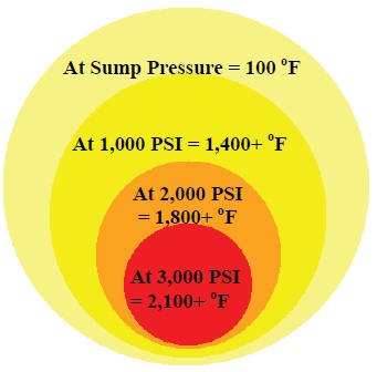 Figure 2. The temperature effect of compression on air bubbles passing through a 3,000 PSI circulation/hydraulic system.
Heat.
Figure 2. The temperature effect of compression on air bubbles passing through a 3,000 PSI circulation/hydraulic system.
Heat. Excess heat makes all of the previously noted problems worse. The Arrhenius rate rule in organic chemistry tells us that chemical reaction rates double with each 10 temperature increase. Following that logic, as sump temperatures increase the aging process increases, doubling with each 10 C increase.
Heat is transferred to the sump from high process temperatures, from surface friction, from cavitation and from shear stress on the oil film as it thickens under pressure.
CONTAMINANT EXCLUSION
Machine owners have tolerated these common contaminants for so long that it is difficult for many of them to change their paradigms and face their challenges. Unfortunately, it is difficult to observe the process of degradation imposed by most contaminants and actually impossible with some. For instance, the solid particle sizes that impose the greatest threat to machine surfaces, those that are small enough to get between the surfaces and bridge the oil film gap, are well below visibility without a microscope.
Since lubricant sumps can be grossly contaminated with solids that cannot easily be seen, severe problems become ignored until much damage is done. Operators must change the way these problems are observed before they are likely to change the way that machines are managed.
Figure 3 illustrates the concept of a dynamic sump and identifies common sources of contamination. The three primary avenues through which contaminants enter tribological systems, whether oil circulation or grease sumps, are breather vent ports, seals and fill ports (with lubricant replenishment).
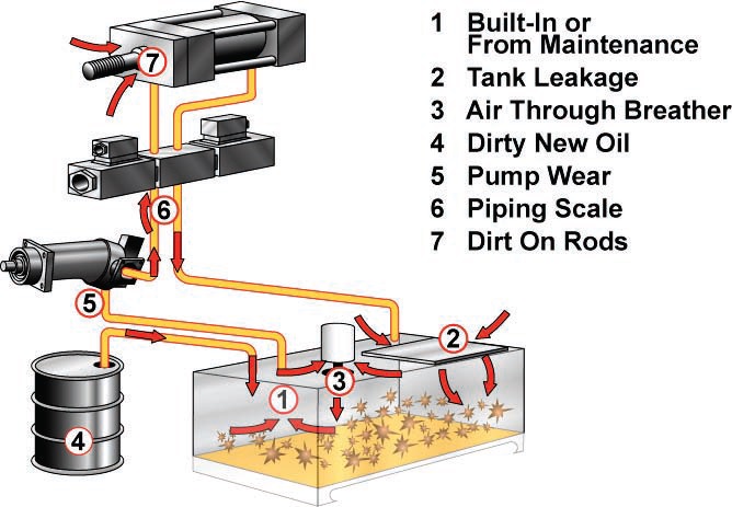 Figure 3. Hydraulic system components and points of ingression. (Courtesy of Schroeder Filtration)
MOISTURE PREVENTION
Figure 3. Hydraulic system components and points of ingression. (Courtesy of Schroeder Filtration)
MOISTURE PREVENTION
Oil cloudiness often indicates when the oil is saturated with moisture but doesn’t help identify the source. In humid climates some moisture comes from the air the machine “breathes” as it heats and cools and as the machine volume cycles in and out of the reservoir. Desiccant vent filters minimize water by absorbing humidity from the moving air as it enters the machine. When functioning properly, vents allow exchange of air across a sump opening with limited risk of gross contamination from water, large particles, process chemicals, rain drops, etc.
Porous and/or poorly maintained vents allow large concentrations of airborne contaminants to enter a system. Vent quality should be evaluated against the quality of the fluid filters used onboard the machine, should have pore tolerances better than the onboard oil filters and be appropriate to support ISO Cleanliness targets.
High quality desiccant breathers also prevent solid debris contamination. Figure 4 shows the likely result of breather neglect. Figure 5 shows a common OEM breather-filler cap, and a useful replacement configuration.
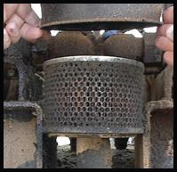 Figure 4. An experienced hydraulic tank vent port at a wood products facility.
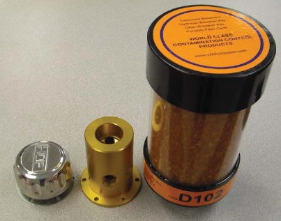
Figure 5. A chrome OEM breather vent and the upgrade desiccant element and mounting base.
SHAFT AND CYLINDER SEAL POINTS
Shaft seals and hydraulic piston wiper and seal points represent likely points for solid and moisture contaminant ingression. Figure 6 represents a lip seal configuration, and Figure 7 shows a typical bearing isolator. Lip seals have a contact fit with the shaft and, by design, press against shaft during operation. These are useful for containing the lubricant within the housing more so than prohibiting contaminant from entering across the contact point.
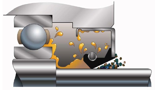 Figure 6. Heat, solid contaminants and rubbing contact degrades lip seals.
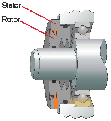
Figure 7. A typical bearing isolator. (Courtesy of Trico Corp.)
Seal condition is rapidly degraded from machine and frictional heat, from rubbing contact with the shaft and/or from three-body abrasive wear following contact with airborne and sump contaminants. The tell-tale indicator that atmosphere is leaking into a machine through a shaft point is the wetted surface that is covered with airborne dust and debris just below the shaft or cylinder. Bearing isolators, as shown in Figure 7, provide a significant reduction in moisture or airborne contamination across the shaft.
Bearing isolators maintain a tight fit with both the housing and the shaft and only experience rubbing contact where the stator fits with the rotor. This allows for better lubricant sealing, better contaminant prevention and both for a longer period of time.
Shaft seals, hydraulic cylinder seals and wipers are composed of polymeric materials and have a limited performance life cycle. There can be a wide quality gap between apparently similar components based on the chemical makeup of the polymers. Performance criteria for resistance to abrasion, to changes in material stiffness and to degradation from lubricant incompatibility should be established for new machines and replacement components specifications.
Maintaining debris and moisture-free external piston surfaces helps extend seal and wiper life and prolong component operating cycles. Hydraulic component manufactures can supply a “boot” or flexible passive covering that can be installed on a new machine before operation. Figures 8(a) and 8(b) illustrate a cylinder before and after fitting with a weather barrier.
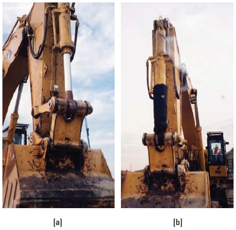 Figure 8. Before and after the seal savor is placed in service. (Courtesy of Fluid Control Services, Inc.)
Passive shields and component covers can be installed on or near high-temperature components as a means for controlling radiant heat transfer through lines and components and back to the sump. Additionally, passive shields may be used to minimize the harmful effects of sunlight, extreme cold, precipitation and airborne solid debris.
AIR CONTAMINATION
Air contamination in circulation systems often can be resolved by assuring high quality sealing at the shaft input to the pump, by assuring that the inlet conditions are acceptable for the system flow requirements and by assuring that oil doesn’t churn upon return to the tank.
Figure 9 demonstrates a proper configuration for a hydraulic return, with the oil returning below surface into the side of a baffle. The return line positions prevent churning more air and promotes release of any present air by delivering it toward the top of the tank and drawing from the bottom of the tank. The baffle is perforated but has enough of a lip to help larger debris settle instead of passing through to the inlet.
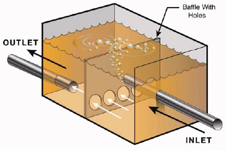 Figure 9. Proper oil return helps prevent churning and foaming.
Figure 10 illustrates another useful addition to a return line. The diffuser slows the return of oil to the tank. Combined with the perforated plate, a diffuser causes the warm oil to mix more uniformly with the tank oil, and the mesh helps agglomerate bubbles for more rapid release.
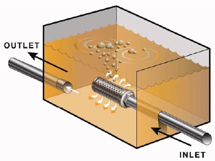 Figure 10. A diffuser slows the passage of the oil back to the inlet and helps release air.
CONTAMINANT REMOVAL
Figure 10. A diffuser slows the passage of the oil back to the inlet and helps release air.
CONTAMINANT REMOVAL
Much of the battle waged for lubricant and machine sump condition control can be won with aggressive prevention efforts—but not all. Routine maintenance, machine shock loading and operating condition upsets (leaks, spills, surges), sloppy handling of the lubricants all contribute to the need for a contaminant removal plan.
The majority of contaminants that find their way to the lubricant sump can be removed. Options even exist for some of the chemical contamination challenges, but by the time chemical contaminants are scavenged from the oil (by means of polar media) additional work is often required to repair the additive integrity of the oil. Unless it is a very large volume of oil, or very expensive oil, it is more economically prudent to replace the sump contents following chemical contamination.
Figure 11 provides a snapshot glance at common contaminant threats and the methods that are used to address those threats.
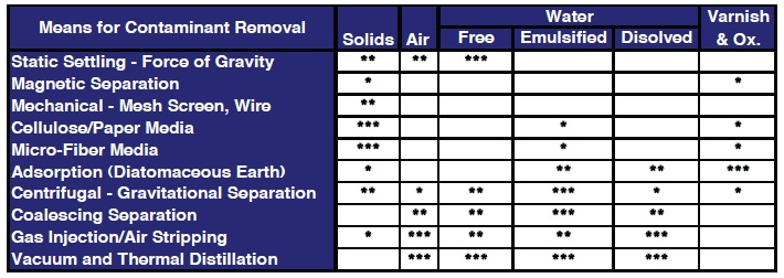 Figure 11. Common methods for removing contaminants.
Following review of oil analysis results, identification of the nature and extent of the contaminant problem in comparison to the stated alarm limits, the next step is to select a removal method.
MOISTURE AND AIR CONTROL
Aside from actual oil analysis results (water in percentage or parts per million), other tell-tale indicators point to evidence of moisture and air contamination. Reservoirs should be reviewed for evidence of condensation on the tops or sides of the lube oil tanks and for evidence of moisture accumulation at the bottom of tanks. Super-saturation in the (headspace) air above the oil can be minimized with a through force draft of filtered air applied to the tank air space, which is not unlike putting the flow from a large hair dryer across the tank. Desiccant elements, such as the one in Figure 5, may be adequate for small hydraulic and stead flow circulation systems but may not accommodate the air flow requirements of a high flow capacity hydraulic system. Where water and air contamination cannot be controlled by these other means, vacuum distillation and thermal exchange filters can complete the task.
Thermal control. Thermal control includes adding and removing heat. Normal machine operation will heat the oil in nearly every mechanical system if the oil is warm enough to enable system startup. Particularly for hydraulic systems that face cold-start conditions, heat may need to be added. Typically, heat needs to be removed from the oil. Sizing thermal controls will be addressed in a future article covering static sump contamination management.
Solid contamination control. Entire textbooks address the issue of solid particulate contamination. An excellent and highly recommended text that addresses the breadth of this entire topic with a strong reliability theme is Dr. E.C. Fitch’s
Proactive Maintenance for Mechanical Systems (
3).
Modern circulation and hydraulic designs should incorporate a combination of elements for different functions. Pump screens prevent system debris, returned to the tank, from re-entering and corrupting the pump and other components. High pressure in-line filter elements are used as last chance protection for critical and sensitive components such as CNC control mechanisms. These elements are designed to capture and hold solid particles, even though they endure extremes in pressure and flow surges. The low-pressure return line element is a tight sieve intended to capture large debris created by lost sealing functions and degradation of major components. Effective designs also incorporate constant flow, low pressure, high efficiency and side stream elements. These high efficiency filter-loops can be devised and operated in such a way that they become the predominant part of the particle scrubbing system.
High criticality systems that lack any of these design features should be evaluated for retrofit. At the minimum, when existing systems do not have continuous filtration, the engineer should recommend the addition intermittent or permanently installed side stream filtration. The decision is dependent on the rate of ingression and the system sensitivity to particulate.
For all machines, it is appropriate to evaluate each pressure, return and side stream element to assure adequate quality to fulfill reliability needs. The filter industry relies heavily on statistical quality testing to measure the capture efficiency of individual element designs. Each element should have a Beta (β) efficiency rating for the sake of element quality comparison. Although the Beta rating does not necessarily guarantee effective performance (due to the many variables that influence hydraulic circuit function), it is a useful start for quality comparison.
Finally, some machines lack both thermal and particulate control features. For these “un-treated” sumps, the lubrication technician and reliability engineer should evaluate the systems’ historical reliability, determine if the pattern fulfills future production requirements and make decisions from improvement modifications.
REFERENCES
1.
SKF Bearing Co.
2.
Behavior of air during adiabatic compression, per Boyle’s ideal gas laws
3.
Fitch, E.C. (1992),
Proactive Maintenance for Mechanical Systems, FES Inc., 5111 N. Perkins Road. Stillwater, Okla., 74045
 Mike Johnson, CLS, CMRP, MLT, is the principal consultant for Advanced Machine Reliability Resources, in Franklin, Tenn. You can reach him at mike.johnson@precisionlubrication.com
.