Strategic oil analysis: Setting the test slate
Mike Johnson & Matt Spurlock | TLT Best Practices May 2009
Primary and secondary tests can identify the causes leading to lubricant failure and provide keys to the solution.

KEY CONCEPTS
•
Just as humans undergo medical tests to understand their health, conducting oil analysis provides insight into the health of a machine.
•
The objective in test selection is to maximize the information gained from a relatively narrow and cost-effective set of tests.
•
Primary tests provide a broad view of health indicators (oil health, contaminant load, machine health) with relatively few tests.
•
Secondary tests provide much more specific types of information that closely pertain to the type of machine being analyzed.
Oil analysis (hereafter referred to as OA) is the control tool that the reliability engineer uses to grade the effectiveness of machine lubrication practices and activities. This article looks more thoroughly at some of the tactics introduced in Part I of this five-part series.
Specifically, this article introduces ideas that should be considered when developing a machine and lubrication practices diagnostic program based on oil analysis, including:
•
Defining a test profile for industrial machines, aka the test slate.
•
Differentiating between primary and secondary tests.
•
Identifying primary test methods, their purpose and benefits.
•
Identifying secondary tests, their purpose and benefits.
Part I addressed the purpose and strategy for effective machine condition monitoring via oil analysis. This aspect of program development should not be overlooked. Without a clear purpose and vision, the plan may fail. So before proceeding with the next steps, double check to see that your purpose and strategic plans are clear.
DEFINING THE TEST SLATE
Just as humans undergo a battery of tests to understand the state of their health, conducting oil analysis provides similar insight into the health of a machine. Subtle changes in the chemical health of the oil/lubricant and in the cleanliness of the machine’s sump as well as increases in the types and concentrations of wear metals, point to solvable problems. When the analysis is conducted systematically, the relative state of machine health can be observed. Armed with information about the machine’s changing health, the machine owner can adjust operating and maintenance practices to protect the machine’s long-term usefulness.
As is the case with human health monitoring, there are hundreds of tests that could be recommended to deliver a particular piece of the puzzle representing overall health. A key to health management, whether man or machine, is understanding which test to use and what to look for within that test.
There are 702 discrete petroleum and lubricant tests listed in the 2009 ASTM catalog. Some of these tests tell of broad characteristics about the test specimen, and some tell of narrow concerns. In addition to the ASTM methods, there are several other standardization organizations providing test methods, including DIN (German Institute for Standardization), ISO (International Standards Organization), SAE (Society of Automotive Engineers), API (American Petroleum Institute) and IP (Institute of Petroleum Test Methods). Each has standards and test methods useful for measurement of a variety of lubricant properties.
PRIMARY VS. SECONDARY TESTS
With the depth of options available, starting from scratch to define the preferred test methods could be confusing and time consuming. Fortunately, through the work of many private labs, individuals and organizational subcommittees, the detailed review and selection of testing methods provides users of oil analysis with a narrow set of suggested options.
The objective in test selection is to maximize the information gained from a relatively narrow and cost-effective set of tests. A fully optimized test slate will include routine (primary) tests providing broad but shallow details, followed by non-routine (secondary) tests providing narrow but more comprehensive details. The secondary tests may be set to occur automatically when specific conditions are met.
The primary test slate provides a broad view of health indicators (oil health, contaminant load, machine health) with relatively few tests. The secondary test slate provides much more specific types of information that closely pertain to the type of machine being analyzed.
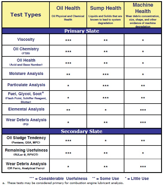
Table 1 indicates the types of tests that are desirable for primary and secondary test slates. There are multiple ways to measure a given item such as oil health. Suggested ASTM methods and a description of the methods are noted below.
Table 1. Commonly Adopted Tests and Their Utility for the Three Functions of Oil Analysis
 VISCOSITY (ASTM D445)
The lubricant viscosity is the most significant parameter to consider for successful machine lubrication. Fluid viscosity impacts frictional losses from component interaction and from viscous drag. Regardless of other conditions, without the appropriate operating viscosity machine components cannot achieve their engineered life cycles. Changes in viscosity also point to other potential causes of future failure.
Viscosity is a measure of a fluid’s internal resistance to flow. The unit of measure produced is typically the centistoke (cSt). It is determined by measuring the length of time, in seconds, required for a fixed volume of fluid to flow a known distance through a narrow tube (capillary) in a calibrated viscometer under a reproducible head of pressure at 40 C and 100 C. An example of common capillary tubes is shown in Figure 1.
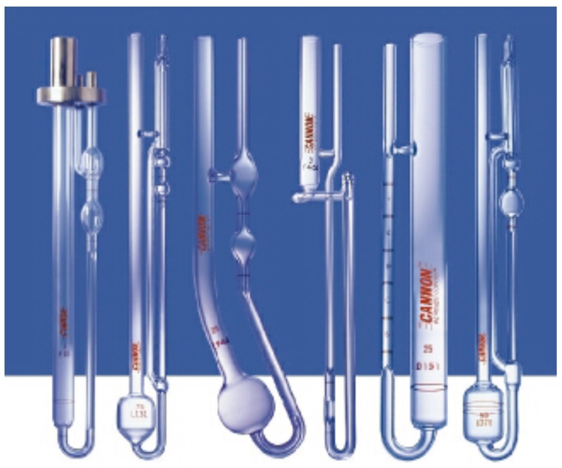 Figure 1. Typical capillary tubes used for viscosity analysis. (Courtesy of Cannon Instruments)
Lubricant viscosities change over time. As lubricants age and experience oxidative and thermal stress, viscosities typically increase. Additionally, a variety of common contaminants can cause the viscosity to decrease. These contaminants also may be oxidation catalysts that accelerate the lubricant’s aging process and ultimately shorten the health of the tribosystem. When a viscosity change is observed, it is imperative that the cause of change be identified and corrected (
see Table 2).
Table 2. Factors That Initiate Change in Lubricant Viscosity
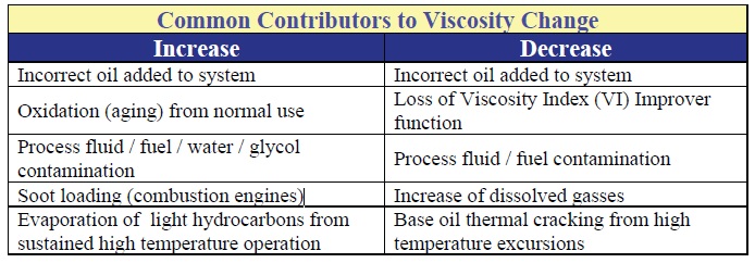
For industrial machines, typically reflecting low-temperature operations, the most common and most easily correctable cause of a sharp change in viscosity is from top-up with the wrong viscosity oil.
Other tests can provide insight into the nature of viscosity changes, including:
1.
Elemental analysis: looking for chemical indicators of incorrect oil (additive metals).
2.
Elemental analysis: looking for presence of glycol (additive metals).
3.
Infrared spectroscopy: looking for oxidation, thermal degradation, chemical contamination, soot loading.
4.
Acid/Base number: looking for evidence of oxidation/chemical degradation.
5.
Karl Fischer, moisture analysis: looking for presence of moisture.
6.
Flash point analysis (automotive): looking for presence of fuel.
FOURIER TRANSFORM INFRARED SPECTROSCOPY
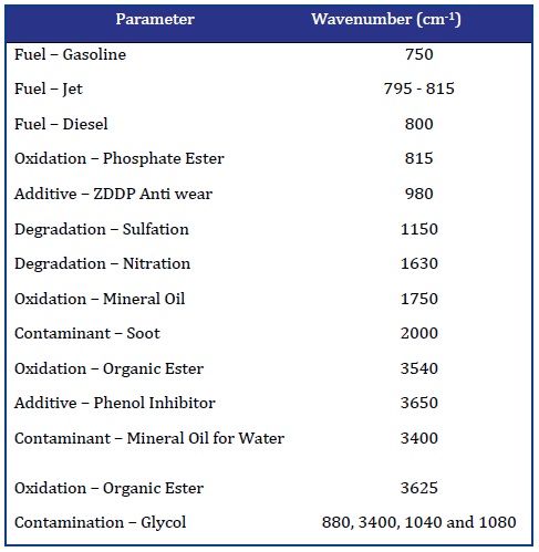
FTIR spectroscopy provides a means to monitor multiple oil parameters simultaneously. To perform the test, infrared (IR) energy is passed through a fixed thickness of oil in the test cell. The IR energy is absorbed at frequencies that are specific to the sample’s constituents (contaminants, oxidation compounds, additives, base oil). The energy signal is processed through a mathematical (Fourier Transform) function to create a frequency spectrum of the transmitted or attenuated (absorbed, reflected) infrared energy. The spectrum of the used oil is compared to a new oil reference for comparative analysis of additives (additive metals, other complex additive compounds), degradation compounds (products of oxidation, nitration, sulfation, other oil waste) and contaminants (water, glycol, soot, chemicals, additive metals).
Infrared spectroscopy evaluates the oil’s constituents at a molecular level where other commonly used spectroscopy methods evaluate the constituents at an atomic level. This distinction is important when looking to verify the presence of fully functioning additives, and/or specific contaminant and degradation byproducts. To perform the test, infrared (IR) energy is passed through a fixed thickness of oil in the test cell. Contaminants and degradation byproducts are (
see Table 3):
Table 3. Common Conditions Reviewed with Infrared Spectroscopy
 ACID NUMBER: ASTM D664 OR D974
When machine lubricating oils oxidize (age), small amounts of acidic byproducts form, causing an increase in the amount of acid that is reflected in the lubricant’s Acid Number (AN). AN, sometimes referred to as Total Acid Number (TAN), is a measure of the total acid concentration of the oil. It is expressed as the volume (milligrams) of potassium hydroxide (KOH) required to neutralize acids present in a one-gram lubricant sample. AN can be measured by either potentiometric (ASTM D 664) or colorimetric (ASTM D974) titration methods. D664 is best for measurement of dark colored oils (
see Figure 2).
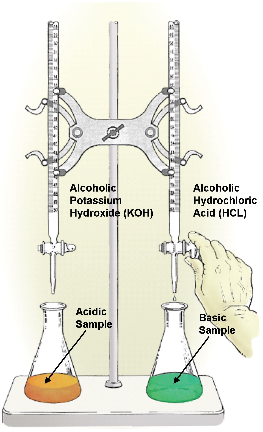 Figure 2. ASTM 974 – Colorimetric analysis test stand for AN and BN measurement. (Courtesy of Condition Monitoring International (CMI))
Antiwear (AW), extreme pressure (EP) additives and some corrosion inhibitor additives can create high initial AN values, but these oil constituents are not harmful. Over time the starting AN value should decrease slightly with additive depletion and then rise with the accumulation of degradation compounds. The current test results should be compared to the new oil results to determine the amount of change that has occurred. AN values above 4.0 are considered to be potentially corrosive, but where the starting points are high (with the use of particular AW agents such as organic moly compounds) the judgment call should be left to the lubricant manufacturer. Generally speaking, high AN values suggest the oil’s useful life is over, and the sump should be changed. Slow increases over a long time period is considered normal.
Rapid changes may be caused by one or more of the following:
•
Cross contamination with high AN oils (EP, AW oils)
•
Mixing with aftermarket agents designed to improve wear resistance
•
Oxidation from cavitation (localized heating)
•
Oxidation from prolonged air entrainment or other operational factors
•
Additive depletion.
BASE NUMBER – ASTM D4739 (PREFERRED) OR D2896
Base Number (BN) measures the reserve alkalinity of engine oil. Engine oils are equipped with additives that provide an overbase condition (alkaline reserve) intended to neutralize acids produced during normal operation. As fuel passes through the engine and the engine oil’s alkaline reserve is consumed, the BN trends downward. Once this reserve is depleted, engine oils can become corrosive.
The test methods are similar to the AN measurements, but with BN the alkaline oil is neutralized with hydrochloric (ASTM D4739-preferred for used oil analysis) or perchloric acid (ASTM D2896). The results are reported in the same units (mg KOH/gram sample) as the AN, but in this instance the BN reading represents the volume KOH base that is required to neutralize the reagent acid used to neutralize the tested sample.
When BN reaches 20% of the starting point, the oil must be changed. Rapid changes in BN may be caused by a variety of conditions, including the use of high sulfur fuel, poor air-to-fuel mixtures, incomplete combustion, gaseous blow-by, high soot levels, coolant contamination (glycol) and overextended oil drains.
WATER TESTS
Water is highly damaging to both lubricant and machine parts. Common water sources include moisture from the air, leaking heat exchangers, direct impingement from the process or from the atmosphere, vapor from the process and human error (wash-down and top-up activities). Water causes or accelerates machine component corrosion (rust), contributes to the formation of bacterial growth, accelerates base oil degradation/ oxidation and degrades and depletes additives. Additionally, large water concentrations can create stable emulsions that mix with oxidation byproducts to form sludge and hard deposits and can collapse the load bearing oil film, causing machine wear and poor reliability.
Moisture analysis by Karl Fischer method reports water content as either concentration in parts per million (PPM) or percentage of the total water (free, emulsified and dissolved) in the oil sample. During testing, the sample is titrated with iodine containing Fischer reagent to an electrometric endpoint. Because test accuracy can be influenced by sulfur-containing AW and EP agents and some rust-inhibitors, the co-distillation method is preferred for lubricants with sulfur-containing additives.
PARTICLE COUNT-ISO 11171 CALIBRATION WITH ISO 4406-99 REPORTING
Solid particle intrusion into the oil sump leads to fatigue wear and to two- and three-body abrasive wear. Particulates enter machines through seals, breathers, from the new oil supply and from filter element pulsation and collapse. Machine wear debris also contributes to increased particle concentrations.
Particle shape, hardness, size and concentration each influence the wear mechanisms that particles produce. It is necessary to be able to measure particle concentrations of a given size in order to understand the usefulness of efforts to reduce particle concentration.
The ISO particle count method provides a number for particles by size and concentration for a quantity of fluid, usually 100 milliliters. Following the ISO 111711 calibration standard, particles and ISO code values are reported according to three particle size ranges: >4 μm, >6 μm and > 14 μm. The ISO Solid Contaminant Code is used to abbreviate the particle concentration expression according to the ranges displayed in the ISO 4406 Range Chart, as shown in Table 4. This approach allows the practitioner to communicate particle concentration data quickly and concisely.
Table 4. ISO 4406 cleanliness Range Chart
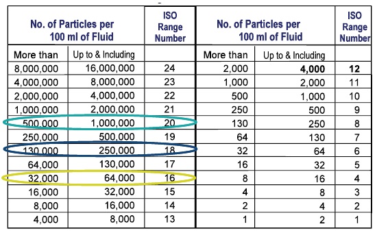
Particles counters may employ light or pore-blockage techniques to automatically estimate the concentration of particles by size per each unit of oil (1 ml or 100 ml). Manual optical (microscopy) methods may be used to eliminate interferences from contaminants (water, air) and oil color (soot, oxidation darkening). Regardless of the method selected, the same method should be used routinely to avoid instrument induced error. Additionally, instrument sensitivity requires that particle counting methods, including sample preparation, be accurate and well defined and that calibration activities be conducted frequently to assure sample-to-sample accuracy.
ELEMENTAL SPECTROSCOPY
Elemental spectroscopy measures for dissolved and some portion of undissolved inorganic materials by element type. Rotating disk electrode (RDE) and argon plasma torch (ICP) spectrometers are atomic emission instruments. These instruments work by exposing the sample to extreme temperatures generated by either an arcing electrode or an argon plasma torch. The heat produced by the source vaporizes the atoms, causing them to emit energy in the form of light. Each element emits light at a specific frequency. The spectrometer quantifies the amount of light generated at each frequency and calculates the concentration of at least 15 and typically 18 common additive and machine elements (iron, lead, silicon, zinc, etc.) in parts per million (ppm) for machine condition oil and sump health reporting, as shown in Table 5.
Table 5. Typical Spectrograph Elements Profile
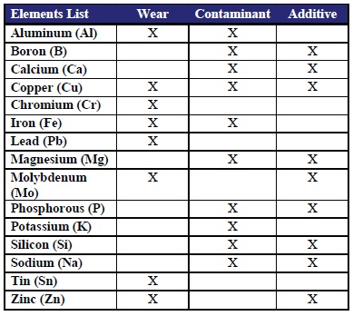
Atomic emission spectroscopy is particle-size limited, diminishing in accuracy as particle sizes approach five microns. This limits instrument effectiveness at diagnosing aggressive wear patterns producing wear debris particles above 10 microns.
PENTANE INSOLUBLES⎯ASTM D893
A degrading lubricant produces high molecular weight compounds. These compounds build up to form varnish layers and deposits in the machine sump and piping systems. Growing levels of pentane insoluble compounds point to lubricant degradation and risk of deposit and varnish formation.
The pentane insolubles test involves mixing the sample with a volume of pentane and then centrifuging the mixture to separate the insoluble oil waste. The residue is removed from the test tube, dried and weighed to provide a test result.
GLYCOL-ASTM D4291 OR ASTM D2982
Glycol contamination is a problem particularly associated with combustion engines. Glycol typically enters an engine sump through a seal failure or a leak in the cooling system. Glycol is particularly harmful to the lubricant, the filter element and the engine due to a variety of possible problems, including the formation of deposits, the formation of abrasive oils balls, plugging of filter elements and risk of corrosion to the engine.
Some antifreeze formulations contain sodium, magnesium, potassium and boron-based corrosion inhibitors. Baselining the coolant will tell the analyst about the metals and their ratios. When these metals appear in the same ratios in the engine oil, it is an indicator of likely glycol contamination.
Elemental analysis is the most sensitive method for glycol monitoring in used engine oil. The coolant is tested to create an element profile and ratio baseline. This is used for comparison to future engine oil samples. Additionally, since FTIR is already in use for many other engine oil analysis measures (measurement for presence of soot, fuel, oxidation, nitration, sulfation), it is also used as a screen for glycol contamination. FTIR sensitivity for glycol measurement is low, however, and requires confirmation if any evidence of contamination is noted.
Schiff’s reagent (D2982) is a colorimetric method that can be used as a screen, either in the lab or in the field. A color change is produced by the chemical change between the Schiff’s reagent and the glycol-contaminated oil when mixed. This method only works when the coolant is still in a molecular (liquid form).
FLASH POINT TEST—ASTM D92
When fuel passes between engine rings and cylinder walls and accumulates in the sump, it lowers the lubricant’s flash point. The flash point test identifies the presence of fuel or other volatile impurities. The test is conducted by placing the oil sample in an enclosed, heated cup. Fumes are produced at an increasing rate as the temperature is increased. At some point the lubricant produces vapors at a high enough rate that the vapors will combust when exposed to an open flame. The vapors are periodically tested, and when the flame is produced the test temperature is noted, and compared to a baseline for a pass/fail result.
RPVOT TEST—ASTM D2272
The Rotating Pressure Vessel Oxidation Test (RPVOT) uses a bomb (a pressurized vessel) to evaluate the remaining oxidation resistance of the oil. A quantity of the lubricant is placed in the bomb along with water and copper coil catalysts. The bomb is pressurized with oxygen to 620 kPa (90 psi), and placed in a 150 C bath at an angle, and the sample is rotated at 100 RPM. The analyst observes for a specific drop in gauge pressure and notes the test duration in minutes. This value is compared to the baseline value (in minutes) to gauge remaining life left in the oil. While useful, this test should be used in collaboration with the other previously mentioned oil stability tests, and not serve as a stand-alone indicator. Some antioxidant additives can greatly extend RPVOT values but produce high quantities of oil waste as the oil degrades.
FERROUS DENSITY MEASUREMENT
When machine wear conditions escalate, the machines produce increasingly larger wear debris particles, which unfortunately are not recognized in the common elemental analysis techniques. A ferrous density measurement can be used as an planned exception following new evidence of abnormal wear, including increasing wear metal concentrations as measured by elemental analysis or increasing particle count for large (>6, >14 micron) particles.
The Particle Quantifier (PQ) and Direct Reading (DR) Ferrography methods are both appropriate for routine and exception testing to identify the onset of aggressive wear, and to project increases in the rate of the problem. Since the readings differ, it is best to determine and standardize to the test of choice.
 Looking to the future, a variety of tests are being adopted that may well displace some of the older standards.
ANALYTICAL FERROGRAPHY
Looking to the future, a variety of tests are being adopted that may well displace some of the older standards.
ANALYTICAL FERROGRAPHY
Analytical ferrography typically occurs after identification of abnormal wear conditions produces an assumption of impending failure, though when coupled with vibration analysis, thermography, Spike Energy™ (Peak Vue,™ SEE™) this technique can be used to avert impending failure. Analytical ferrography involves the microphotograpic analysis of ferrous debris deposited onto a glass slide (ferrogram) or captured on a filter membrane (filtergram). Evaluation of wear particle characteristics, including size, shape, texture, reflectivity, color, surface appearance, angularity, edge details, elemental content and relative concentration, offers indications of the severity and type of a wear condition.
The analyst typically also reports evidence of fibers, amorphous (shapeless) deposits, presence of dirt and sand, wear polymers and other (nonferrous) deposited metals. Diagnosis of a root cause (two-body adhesive wear, three-body cutting wear), suggestion of the components involved, conclusions and recommended corrective actions accompany commentary and photographic evidence.
SUMMARY
There are many test methods with varying degrees of utility, but relatively few are commonly used for used machine and engine oil evaluation techniques. Primary and secondary lubricant test methods should be defined according to the type of machine under review. Secondary tests may require owner intervention, but if properly selected and triggered the owner can save time by having these more invasive and sometimes more expensive tests automatically conducted as needed. The test methods reviewed in this article are common to most commercial labs and should be thoroughly understood by users of oil analysis.
Looking to the future, a variety of tests are being adopted that may well displace some of the older standards. The Micro Patch Calorimetry (MPC-oil health), Linear Sweep Voltammetry (LSV, RULER-additive health), Scanning Electron Microscope Energy Dispersive X-ray Analysis (SEM/EDX – wear debris analysis) and Laser Net Fines (wear debris analysis) are each highly sophisticated and effective methods for diagnosing and characterizing conditions of failure and/or conditions that may lead to failure.
 Mike Johnson, CLS, CMRP, MLT, is the principal consultant for Advanced Machine Reliability Resources, in Franklin, Tenn. You can reach him at mike.johnson@precisionlubrication.com
.
 Matt Spurlock, CMRP, MLA II, MLT I, LLA I, is the machine lubricant subject matter expert at Allied Reliability, Inc., in Indianapolis, Ind. You reach him at spurlockm@alliedreliability.com
.