Lubricant application: Grease volumes and frequencies
Mike Johnson, Contributing Editor | TLT Best Practices April 2009
Developing a consistent and systematic replenishment approach can go a long way toward ensuring the quality of your relubrication practices.
KEY CONCEPTS
•
Calculating the volume and frequency of lubricant can be determined by using two simple approaches.
•
Automatic lubrication systems are now being incorporated in modern grease application methods for geared machines.
•
Proposed grease application volumes are based on gear size, speed, lubricant type and lubricant application method.
In previous articles we’ve addressed lubricant selection for all types of components. This month we’ll address grease type lubricant application methods for common grease lubricated components.
Unlike oil application, applying grease to components holds a bit of mystery and intrigue. Unfortunately, the mystery part often produces great inconsistency and poor quality on the plant floor.
Most oil reservoirs provide machine operators with a portal through which the operator can determine that the right quantity of oil is in place. Whether the machine’s oil tanks are square-, round- or trapezoid-shaped, the machine designer is expected to provide a simple, easy way to judge oil volume and, hence, oil application effectiveness.
This option doesn’t translate well for grease lubricated machine sumps. Given that grease doesn’t flow so well inside the machine sump, a grease sump viewport would quickly become obscured by grease.
In addition, since there are no transparent materials with the strength of steel from which bearing housings could be constructed, we have to settle with carefully planning the replenishment volumes and then verifying the effectiveness of the practice with readily available measurement tools.
SUPPLY VOLUME: PLAIN AND ELEMENT BEARINGS
Following selection of the best fit grease lubricant, the next step toward creating precise, reliability-centered lubrication practices is to apply the right volume of lubricant at the best or at least a healthy interval. (Note, you can find archives of Best Practice articles addressing selection of appropriate viscometric range and additive structure for bearings and gears in the Members Only area of the STLE Web site,
www.stle.org.)
Grease lubricated applications are nearly always expected to be continuous loss systems. As such, a planned, consistent, systematic replenishment practice is necessary to protect both the grease in the machine components and the components themselves. This article presents grease application and frequency for plain and element bearings.
Plain bearing grease application. There isn’t much printed literature providing practical advice for quantity and frequency of application for plain journal bearings without delving into the original design parameters and operating states. Given that the original design considerations greatly influence the viscosity and supply rates, this is understandable. Following the OEM’s advice should be fully considered before proceeding with a model that doesn’t include all of the designer considerations.
Grease replacement volume for plain bearings is influenced by several key factors that influence the replenishment requirement (flow rate) for a plain bearing, including lubricant product type (oil, grease), grade (ISO viscosity, NLGI grade), sealing integrity, shaft and element size and surface finish, shaft speed, dynamic loading characteristics, eccentricity, radial clearance, cooling methods, etc.
Each factor should be accounted for in the design process for a plain bearing application.
The practitioner may choose to verify OEM recommendations if the complete set of machine design parameters is available. Experience suggests that the full set of details is difficult to locate once the machine is operating in a production environment. A complete treatment of this topic can be found in
The Tribology Data Handbook (
1) by Michael Khonsari. At a minimum, the OEM’s advice should be fully considered before proceeding with a model that doesn’t include all of the designer considerations.
Assuming the proper product has been selected for the operating state, proper quantity and frequency of lubrication can be estimated using a couple of simple formulas.
Following are two options that are dependable and easy-to-use for frequency and volume calculation.
Option 1—Michael Neale Method. This approach provides the volume in grams per hour. Figures 1 and 2 may be used to calculate the grease replacement volume. The information required is generally easy to obtain. Requirements include bearing dimensions, shaft speed and diametrical clearance. Standardized diametrical clearances for a variety of bearing qualities are provided, both by the supplier and in engineering handbooks.
 Figure 1. Option A for Grease Relubrication Replacement Volume Per Hour (2)
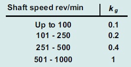
Figure 2. Shaft Speed Parameter for Formula in Figure 1.
This approach does not take into account an operating frequency or the operating environment. Heat, moisture, sealing effectiveness, component mechanical fitness and corrosiveness of the process all influence lubricant coverage and effectiveness. Some instances require the lubricant to serve as a flushing media to reject process chemical and contaminants. In these instances, a factor to increase relubrication frequency should be incorporated to provide the feed volume at shorter intervals.
Option 2—Trabon Lubriquip Method. This approach also assigns lubricant quantity at a projected oil film thickness (1/1000th-inch) and during a given period. This method has been used successfully for many years beginning in the early days of automatic system design and use (
3).
The approach recommends the application of the lubricant (oil or grease) at the rate of 2/1000th film thickness per eight hours for manual lubrication and 1/1000th film thickness per four hours for automatic feed. With this approach the interval is set, or at least proposed, and the volume is calculated based on component surface area.
 Figure 3(a). Graco/Trabon Formula for Replenishment
Surface area calculations differ per type of component. Following are calculations that would be used for grease lubricated journal bearings.
 Figure 3(b). The Graco/Trabon Plain Bearing Dimension Formula
As shown in Figure 4, these two options applied to a tail pulley bearing on a drag conveyor, with bearing dimension of four-inch diameter and eight-inch length, provides similar results for volume during an eight-hour shift. It is difficult to say that one is wrong. Either method both should provide adequate coverage, assuming a quality lubricant is matched to the production demands.
 Figure 4. Comparing the Different Approaches Shows Similar End Result from Fairly Different Standards of Measure
.
The recommended grease volume works best when uniformly distributed during the course of the final time cycle or to the extent that program management can allow. If the calculated quantity was 6 grams per hour, then 1 gram per each 10 minutes would be better than 6 grams at 60 minutes. This is part and parcel in the system engineering thought process for automatic system design. It is more difficult for manual lubrication practices. As a rule, grease lubricated journal bearings should be automatically lubricated anyway.
ELEMENT BEARING GREASE LUBRICATION
Bearing manufacturers have provided a significant amount of detailed advice and simple methods for estimating lubricant type, volume and frequency to match machine operating components and conditions. The object with element bearing lubrication is to place, and then replace, the grease in the housing that is enough to feed oil continuously to the element race but not enough to crowd the elements, which creates churning and heat and degrades the lubricant.
BEARING NET CAPACITY AND INITIAL FILL VOLUMES
When an element bearing is first placed into service, the initial fill material generally fills the vacant space around the elements and between the races. This material may be a corrosion inhibitor or it may be lubricating grease. The initial fill volume can be based on the bearing net capacity as long as there is sufficient space at the sides of the element to allow the excess grease to vacate the element path when the machine is put into service.
In addition to the grease introduced into the element spaces, enough grease should be placed into the housing to bring the grease level up to the lip of the bottom race of the bearing. When the excess from the initial fill is pushed away from the elements it accumulates on the grease shelf at the race and becomes a reservoir to continuously serve oil back to the raceway without crowding the elements.
The bearing net capacity is calculated as follows (
4):
V = ((Pi/4) * W * (OD
2 - ID
2) * 10-9 - G/7800)*106,
where
V = Volume in cubic centimeters
OD = Bearing outer diameter, mm
ID = Bore diameter, mm
W = Bearing width, mm
G = Bearing weight, kg (21.5)
REPLENISHMENT REQUIREMENTS FOR LOW PLV ELEMENT BEARINGS
A replacement volume for low to medium pitch line velocity (PLV ≤ 300,000 for ball and cylindrical roller, ≤ 100,000 for spherical and thrust roller) element bearings is somewhat easier to estimate. Initial fills for very low PLVs can range from 33% to 80%, assuming accurate bearing selection. The initial fill amount can be a higher percentage of the original volume as the PLV declines and vice versa.
As with plain bearings, one should consider both feed volume and frequency. The formula shown in Figure 5 can provide grams or ounces for three different interval types depending on whether the bearing dimension is given in millimeters or inches.
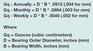
Figure 5. The Element Bearing Replenishment Volume Formula
Where actual bearing dimensions are not known, a close proximity to the actual suggested value could be estimated by using housing dimensions and factoring again by one-third {( D * B * .114)*.33}. This provides only a close approximation. For critical applications the actual bearing make and model should be determined.
REPLENISHMENT FOR HIGH PLV ELEMENT BEARINGS
A replacement volume for high velocity (PLV ≥ 330,000 for radial ball type; ≥ for spherical roller and thrust type) element bearings requires a careful approach due to shearing and heat produced by overfilling. Bearings of any type operating at high speeds benefit from more frequent application of very low doses, emulating with grease the type of continuous replenishment that occurs when the element is oil lubricated.
For instance, the volume calculated for the short interval, Gq-Weekly, would ideally be uniformly distributed into the number of working hours for the time period and applied accordingly. This statement brings into question the periodicity of the relubrication event.
REPLENISHMENT FREQUENCY FOR ELEMENT BEARINGS
A relubrication interval is based on theoretical reduced service life (F10 Real) in hours, which is based on known grease degradation performance under test conditions (FAG tester FE9, SKF tester R0F). The FE9 test is more severe than the R0F, incorporating high axial and radial loading vs. pure axial load.
Grease lifecycles can be predicted empirically. Much like a bearing L10 lifecycle value that indicates an operating interval for which 10% of a given bearing population would fail under identical operating conditions, the grease F10 value projects an operating interval for grease lifecycles and, consequently, relubrication intervals. It is predicated on work conducted by the German Society of Tribology (GfT, worksheet 3), and has been adopted as a viable method to project Frequencies (5).
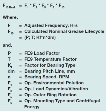
Figure 6. Grease Lifecycle Value Calculation—Useful for Determining Relubrication Intervals
Lubrication interval selections through this method require a very clear understanding of the exact machine operating conditions, bearing details and certainly grease F10 values.
When F10 values for specific products are not available, a modified approach can provide the reliability practitioner with a well-educated starting point. This empirically derived approach assumes nominal operating conditions for bearings operating at low PLV values (≤ 300K for ball and roller type elements, ≤ 140K for spherical and thrust type elements), as follows:
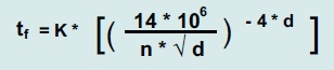
Figure 7. Generic Grease Replenishment Formula
Where,
tf = Time in hours for replacement
K = Product of environmental correction factors
N = Shaft speed
D = Bearing bore in millimeters
The correction factors (see Figure 8) allow the engineer to adjust frequencies based on machine operating and environmental considerations. The six provided conditions reflect practical issues that degrade bearing life and grease performance.
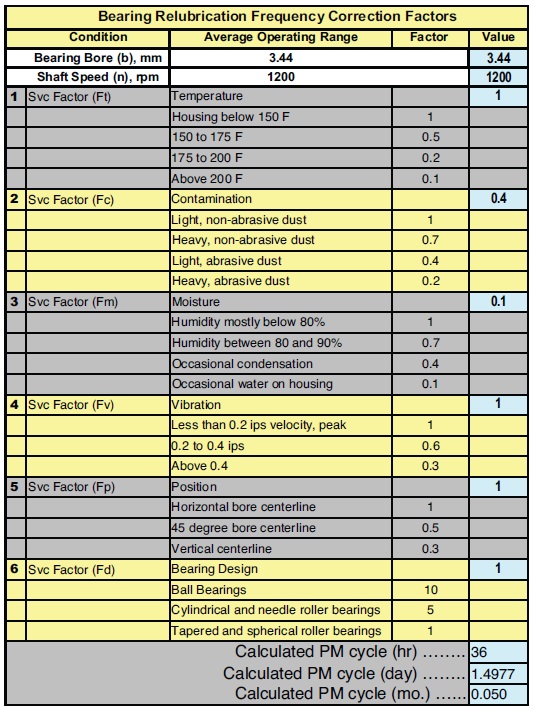
Figure 8. Bearing Relubrication Frequency Correction Factors.
Figure 8 includes the correction factors for a 3.44-inch bore spherical roller bearing operating at 1,200 rpm (PLV = 160,800) in direct exposure to rain and in a dusty environment such as on an unpaved building easement near a roadway and exposed to the weather. The calculated interval amounts to 36 hours between relubrication events. For this short of an interval, an automatic application method is strongly recommended.
Bearing OEM Lubrication Guideline publications provide alternate quantitative approaches that are also valid and could be considered as a strong reference starting point (6, 7, 8).
LUBRICANT APPLICATION
There are various methods that may be selected to add the required quantity to the designated component. The high volume and short frequency applications benefit most from some form of automatic lubrication supply. Semiautomatic (single point automatic lubricator), as shown in Figure 9.
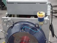
Figure 9. Single Point Lubricators (Courtesy of Trico Corp.)
Most machine grease replacement is still conducted by manual grease gun. This method is labor-intensive and leaves opportunity for the process of lubrication to compromise the effectiveness of the lubricant selected but at the same time provides a means through which the maintenance department can gather useful machine condition information via the skilled lubrication technician on a timely basis. Without machine inspections and feedback from a lubrication technician, manual lubrication is prone to degrading machine productivity and reliability.
Figure 10 shows a fully automatic multipoint automatic lubrication system, typical for use where there are multiple points located in close proximity. Properly designed and installed, these lubricant applicators provide exceptionally good value in terms of the long-term cost per lubrication point and in terms of the reliability potential that this type of automation can provide.

Figure 10. A Multipoint Progressive Grease Lubrication System (Courtesy of Lincoln Corp.)
GEARS
The American Gear Manufacturers Association (AGMA) Technical Bulletins ANSI AGMA 9005 E02 provides background and detailed knowledge for product selection, product performance and volumetric application recommendations for open gear applications (9).
Grease application volumes are proposed based on gear size, speed, lubricant type and lubricant application method. AGMA members have worked closely together to offer their best collective advice to machine owners to optimize lubricant feed frequency and volumes. Similarly to that of bearings, the principal is based on a replenishment of a small quantity of lubricant across the machine contact surfaces for a given amount of time. The faster the machine surfaces come in contact with one another (based on gear pitch line velocity), the greater the quantity of lubricant. Also, the larger the gear surface, the greater the required quantity of lubricant.
Modern grease application methods for geared machines invariably incorporate the use of automatic lubrication systems, as shown in Figure 11.
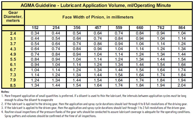
Figure 11. AGMA Recommended Guidelines for Open Gear Volume and Frequencies.
COUPLINGS
Couplings require visual observation during the relubrication process. Proper methods required removing the housing and the old material, examining and replacing the components and hand-packing the components before restoring the housing. Once the housing is in place, grease may be provided to fill the housing until grease is produced at both sides.
Excellent advice is available from most coupling manufacturers, including product selection, viscosity, product volume and application methods per type of coupling. Again, AGMA provides very specific detail on coupling lubrication through Technical Bulletin ANSI/AGMA 9001 B97. This bulletin may be found at the web reference (10, 11). Figure 12 depicts a typical grease spray configuration for grease lubricated gears.
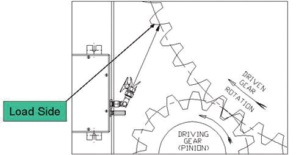
Figure 12. Typical Configuration for Grease Application for Open Gears. (Courtesy of Lincoln Corp.)
CHAINS
Although it is best to lubricate chains with oil, grease is still often used for extended lubrication intervals. Helpful chain relubrication information may be found in the American Chain Association document: Identification, Installation, Lubrication and Maintenance of Power Transmission Roller Chains in ANSI B29.1 and ANSI B29.3 and Fundamentals of Chain Lubrication (12, 13).
SUMMARY
Common machine components such as bearings and gears cannot survive without timely and sufficient relubrication. Grease provides an efficiency opportunity that doesn’t exist with oil lubricated sumps, and accordingly is a common choice by machine designers.
Without the benefit of thoughtful, purposeful practices, grease relubrication methods have the potential to negatively impact component life and machine health. Common methods for plain and element bearings can be used by the lubrication and reliability engineer to greatly enhance the usefulness of grease products.
Automatic lubrication methods should be considered whenever multiple points operate in very close proximity and whenever calculated frequencies are at, or less than, seven days.
REFERENCES
1. Khonsari, M. The Tribology Data Handbook, Chapter 61, CRC Press.
2. Neale, M. Tribology Handbook, 2nd Edition, p. A7.5.
3. Lubriquip Technical Bulletin #20115. Click here.
4. LubCon GMBH, Bearing Lubrication Calculation Worksheet, FAG Bearings, German Society of Tribology and others.
5. LubCon USA, LubCon GMBH, Bearing Lubrication Calculation Worksheet.
6. FAG Roller Bearing Lubrication Guideline WL81115E. Click here.
7. Web Reference X.X - Timken Bearing Co. Click here.
8. Web Reference X.X - SKF Bearing Co. http://mapro.skf.com.
9. American Gear Manufacturers Association. Standard 9005-EO2.
10. American Gear Manufacturers Association. Technical Bulletin ANSI/AGMA 9001 B97.
11. Falk Corp. Installation and Maintenance of Double and Single Engagement Gear Couplings Technical Bulletin 458-110. Click here.
12. Web reference X.X Click here.
13. Wright, J.L., “Fundamentals of Chain Lubrication,” Machinery Lubrication Magazine. Click here.

Mike Johnson, CLS, CMRP, MLT, is the principal consultant for Advanced Machine Reliability Resources, in Franklin, Tenn. You can reach him at mike.johnson@precisionlubrication.com.