Challenges in formulating metal-forming fluids
Dr. Neil Canter, Contributing Editor | TLT Metalworking March 2009
Developing metal-forming fluids for specific applications and increasing manufacturing productivity are just some of the problems facing lubricant suppliers.
KEY CONCEPTS
•
Metal-forming operations are diverse and range from sheet metal-stamping to wire-drawing. Other examples include blanking, coining, drawing, hydroforming, warm and hot forming and rolling.
•
There are several evaluation tests that formulators can use to make sure the right fluid is picked.
•
The Twist Compression Tester utilizes a lab bench procedure for evaluating fluids under several different lubrication conditions.
Metal-forming is a class of metalworking operations that transforms the workpiece metal from its original shape (coil or a sheet) into a functional part. In contrast to metalworking operations that require the removal of metal, metal-forming involves the bending, stretching, ironing and shaping of metal. For example, just think about the body of an automobile. It is typically made from various metal alloys, and the process to manufacture the body requires a series of forming operations to create the right shape based on the design of the part.
In a metal-forming operation, the workpiece is forced through a die which will provide the shape for the finished part. A press or punch imparts the force needed to facilitate the operation.
Metal-forming is one of Mankind’s oldest operations, dating back more than 7,000 years (
1). The first operation carried out was to prepare tools, utensils and weapons through the use of a metal-forming process called forging.
Metal-forming operations are diverse and can range from sheet metal-stamping, which utilizes large mechanical presses that can weigh 1,100 tons, down to wire-drawing, which utilizes small tooling to draw wires through a die or series of dies. Other examples of metal-forming operations include blanking, coining, drawing, hydroforming, warm and hot forming and rolling (
2).
BASIC FUNCTIONS AND TYPES OF METAL-FORMING FLUIDS
Metal-forming lubricants provide the same basic functions as metal-removal fluids, including lubricity, cooling and corrosion protection. Lubricity is a very important characteristic, especially because the metal-forming fluid needs to reduce friction and act as a barrier to minimize contact between the die and workpiece. The former characteristic is critical because the tool/ die setup in a metal-forming application can be quite involved. After the setup is completed, the expectation is that the tool package will produce large quantities of parts without the need of maintenance.
Heat generation can be a problem during metal-forming, though not to the extent seen in metal-removal (this factor needs to be validated and reduced in every metalworking application by some definitive measure of temperature). Corrosion protection can assume a good deal of importance, particularly after the metal-forming application has been completed. Completed parts may need to be kept in storage for up to six months. This means that a fluid may require a corrosion inhibitor to prevent corrosion under a variety of storage conditions.
A strong understanding of this process flow is essential to ensure adequate protection is maintained throughout. This may require the need for another corrosion preventative to provide extended protection.
Metal-forming fluids are formulated and generally fall into the main types of metalworking fluids present in the industry, which includes neat oils, emulsified (soluble) oils, semisynthetics and synthetic fluids (i.e., water-based—both emulsifiable and solution). Fluid selection is predicated on many key items including application, process, water quality, metal being formed, pre- and post-process needs, equipment type and customer preference. For example, in ferrous wire-drawing, powder-type solid lubricants based on calcium and sodium salts of fatty acids are used.
Additives are incorporated into metal-forming fluids to boost performance. Lubricity is particularly important, as metal-forming operations commonly can occur under boundary, hydrodynamic or a combination of both lubrication conditions. This means the fluid needs to be formulated with fatty oils or ester-based lubricity additives, and, in some cases, extreme pressure agents (
3).
The diversity of applications and fluid types means that metal-forming formulators face major challenges in recommending specific metal-forming fluids for particular applications. Interviews were held with leading industrial experts to obtain their insights into the challenges they face in working with metal-forming lubricants and specific applications.
CHANGE IN FLUID TECHNOLOGY
STLE-member John Steigerwald, vice president for business development for Etna Products Inc., in Chagrin Falls, Ohio, says, “A number of factors need to be considered when recommending a metal-forming fluid. The key consideration is choosing the proper fluid and applying the proper amount of lubricant in the proper places at the proper time. Metal-forming fluids are used in a process, and all the considerations of the process need to be considered when choosing the fluid.”
The result is that the metal-forming lubricant company must have a thorough understanding of the operation. This includes what happens to the metal part, both before and after the application. Steigerwald summarizes, “The metal-forming formulator needs to be a knowledgeable process expert who works with a customer to ensure that all items are identified, discussed and understood prior to making a recommendation. This is not just asking what the customer is using today and coming up with a product to match, because the product being used today might not be the best one for the overall process needs. Rather, the metal-forming lubricant representative needs to be viewed as a technical consultant to provide solutions to the end-user and not just as a lubricant supplier.”
Steigerwald believes the metal-forming industry is looking at changes in lubricant technology to keep up with the process changes end-users are requesting to improve productivity and reduce overall production costs. For example, he says, “The industry continues to seek replacements for the standard phosphorus- and soap-based cold metal-forming coatings. Among the options is a coating that can be dried and applied without the process steps and waste byproducts that exist today in the phosphorus/soap method or even by using other wet media.”
Changes of this nature not only entail a change in the type of lubricant but also lead to a change in how the end-user handles the following: (1.) changes in the process and possibly the equipment, (2.) how maintenance is handled, (3.) training on the new process and the fluid and (4.) which pre- and post-issues need to be understood and dealt with as a result. This is not just a lubricant change but, more comprehensively, a process change that takes a commitment from both the end-user and the lubricant supplier. Change is an asset, but it does not come without the commitment and focus to make it a reality on the part of stakeholders.
Steigerwald emphasizes that a lubricant supplier must not only know his product’s capabilities but, more important, must have the industry and process knowledge to assist in the challenges faced by customers. Concurrently, the lubricant supplier must bring forth true solutions based on technical and engineering knowledge. These solutions must not be just another “me-to” product answer with a lower acquisition price.
IMPACT OF LIGHTER METALS
A second factor that is affecting the types of metal-forming fluids used is the move toward the use of lighter metals such as aluminum, magnesium, magnesium alloys and titanium. Steigerwald attributes this to the need for improving fuel efficiency, conserving energy, improving strength and reducing weight, particularly in the automobile, aerospace/aircraft and energy sectors.
According to Steigerwald, the metal-forming lubricant industry must work with end-users in the design, research and development of future processes, not after they are developed. Working with universities, original equipment manufacturers (OEMs), the metals industry and press and die manufacturers in technical exchange type consortiums is important, because this is where the stakeholders and process elements are discussed.
Another key point is that the technical process change area is clearly a global-oriented need. The research is no longer centered in one area of the world. The reach of lubricant suppliers must allow global connectivity and collaboration.
METAL-FORMING CASE STUDY
A case study illustrating these steps concerns an automotive door hardware manufacturer that built a new 14-station progressive die to manufacture a truck tailgate latch. STLE-member Michael Cesa, market development manager for Etna Products Inc., in Chagrin Falls, Ohio, says, “A series of operations including an irregular draw, hole punching, notching and extrusion are planned for a 400-ton Straightside Press. The entire process needs to be validated because the die and the entire press line are new.”
Initially, the manufacturer encountered serious wall thinning of the metal during manufacture. Cesa adds, “Thinning was as high as 40% in some areas, which exceeds the 20% acceptability rate requested by this end-user. A typical acceptability rate for most applications in general is 10%. The higher acceptability rate for this process is due to its severity.”
The approach taken to reduce the thinning rate was to evaluate the die design through the use of circle grid analysis. In this process, a series of circular patterns are etched on strips of metal placed in a die. Analysis of the local forming patterns enables the degree of thinning to be predicted.
Cesa says, “Circle grid analysis allowed us to recommend that an additional die station be used and that the clearance between the punch be expanded. These options improved the flow of metal, which reduced the degree of metal thinning.”
An emulsifiable oil formulated with boundary lubricity and extreme pressure additives also was recommended based on this analysis of the system. The result was improved performance with the thinning rate reduced to acceptable levels.
DEEP-DRAWING
One metal-forming operation singled out by several fluid representatives as being particularly challenging is deep-drawing of steel. Cesa defines deep-drawing as an operation using a press (mechanical or hydraulic) to draw metal so that the depth of the draw is deeper than the diameter of the punch used. Parts prepared from deep-drawing are shown in Figure 1.
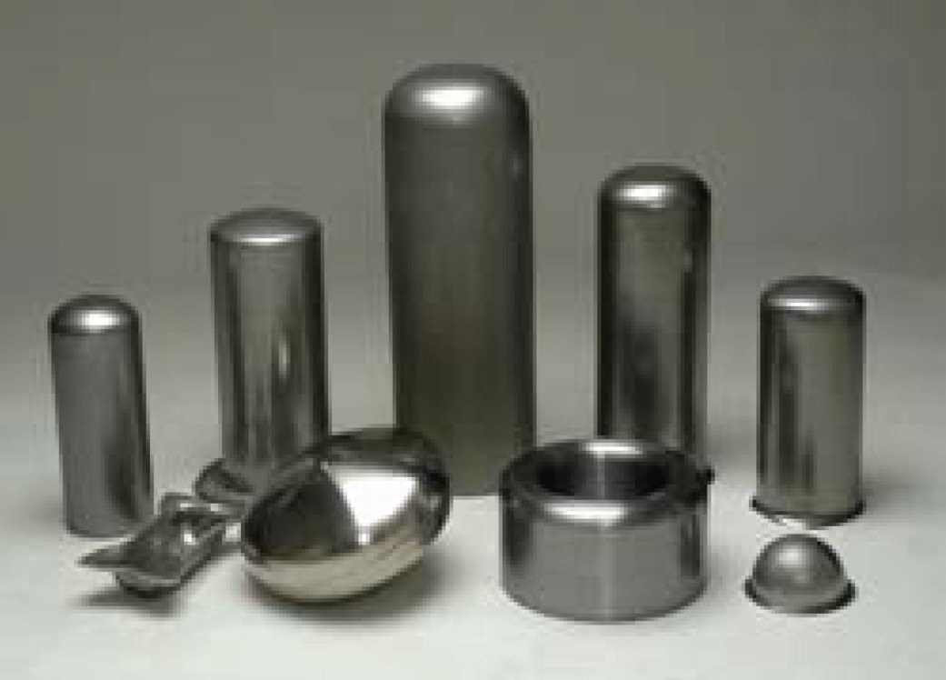 Figure 1. Parts produced by the deep-drawing of metal. This metal-forming operation uses a press to draw metal so that the depth of the draw is deeper than the diameter of the punch used. (Courtesy of Etna Products Inc.)
STLE-member Kathy Helmetag, senior research chemist for Henkel Corp., in Madison Heights, Mich., says, “Deep-drawing leads to an expansion of the surface area of the metal part. During this process, the surface area increases by one to two times the area of the original sheet. An example is making a bath tub out of a sheet of steel.”
The type of metal-forming fluid used often contains extreme pressure additives. Helmetag terms this ironic because the operation is usually run under hydrodynamic lubrication conditions. The metal-forming fluid can have a viscosity of up to approximately 1,000 SUS at 40 C. Helmetag adds, “The metal-forming formulator is not necessarily looking for that high a viscosity, but the additives required to achieve the required performance often lead to a relatively viscous fluid.”
Neat oils and emulsifiable fluids are the main types used. The industry is looking to move away from chlorinated paraffin-based fluids and neat oils for regulatory concerns and cleanability. In the latter case, Helmetag believes this also will improve rust protection on the deep-drawn part and reduce operating costs.
Helmetag says, “The lubricant supplier must evaluate the entire metal-forming operation and focus on the most difficult part of the draw. There are specific areas on the die that are under very high and constant stress during the deep-draw. Steel that is not deformed properly could spring back and grab onto the punch.”
Determining which metal-forming fluids do not work is as important as understanding what fluids do work. Helmetag believes both aspects need to be understood to optimize the product.
Etna’s Steigerwald feels that in deep-drawing processes the lubricant formulator must find the ability to balance boundary vs. hydrodynamic lubrication. He agrees that the trend is moving toward emulsifiable oils, particularly because of their ability to provide cooling. Chlorinated extreme pressure additives have been a main component in deep-drawing oils. But chlorine-free technology has been successfully used in the European Union.
DEEP-DRAWING CASE STUDY
A grade of high-strength steel with a thickness of 0.2 inches was put through a severe deep-drawing operation in the extreme pressure lubrication regime. The end-user used a chlorinated paraffin-based emulsifiable oil and wanted to switch to a chlorine-free product.
Helmetag was tasked with determining whether this application could be done without chlorinated paraffin. Initially, fluid candidates were evaluated in the actual operation. Helmetag says, “We found out which fluids could stamp out parts and which caused parts to fuse to the die or could not be fully released from the die. Based on the results, we then organized the candidate fluids into ‘go-no/go’ pairs for use in lab testing.”
Those fluids that are designated ‘go’ work in the application, while those that are ‘no-go’ failed. To accomplish this task, the end-user must be fully engaged in this process.
Helmetag says, “I imagine there are probably 4,000 tribotests available for use in evaluating lubricants, particularly when you consider all the variations of each method on each instrument. Our approach was to utilize test methods that can evaluate each metal-forming lubricant candidate under elastohydrodynamic, boundary and extreme pressure lubrication regimes.”
The tests selected were the PCS instrument used to evaluate variable slide roll contact in the elastohydrodynamic region, the drawbead tester to measure boundary lubricant characteristics and the four-ball EP tester to evaluate the weld points of these lubricants.
Helmetag found that the four-ball EP weld test could correlate with the ‘go-no/ go’ pairs but could not differentiate the performance of the ‘go’ fluids. She adds, “We then captured the run data and were able to evaluate the friction force curve to determine which of the ‘go’ fluids will work best in the actual application.”
Even then, four to five additional trials were needed to optimize the product, which is a chlorine-free emulsifiable oil. The final deep-drawing fluid is doing well in long-term testing.
Helmetag concludes, “The lubricant formulator needs to go beyond existing laboratory test methods to tailor evaluation procedures so they can correlate with the specific application. Evaluation testing also will need to be distinct for each metal-forming application because unique tribological conditions are found with every die.”
HOT FORGING
Hot forging is a severe metal-forming operation that entails the massive deformation of billets and bars to achieve specific end-products, according to J. Richard Douglas, consultant for the Metalworking Consultant Group LLC in Mentor, Ohio. Douglas says, “Hot forging is typically done above the recrystallization temperature of the metal. In the case of steel, hot forging is carried out at temperatures between 1,150 C (2,100 F) and 1,290 C (2,350 F).” Figure 2 shows a recently produced precision forged bevel gear on a cooling table.
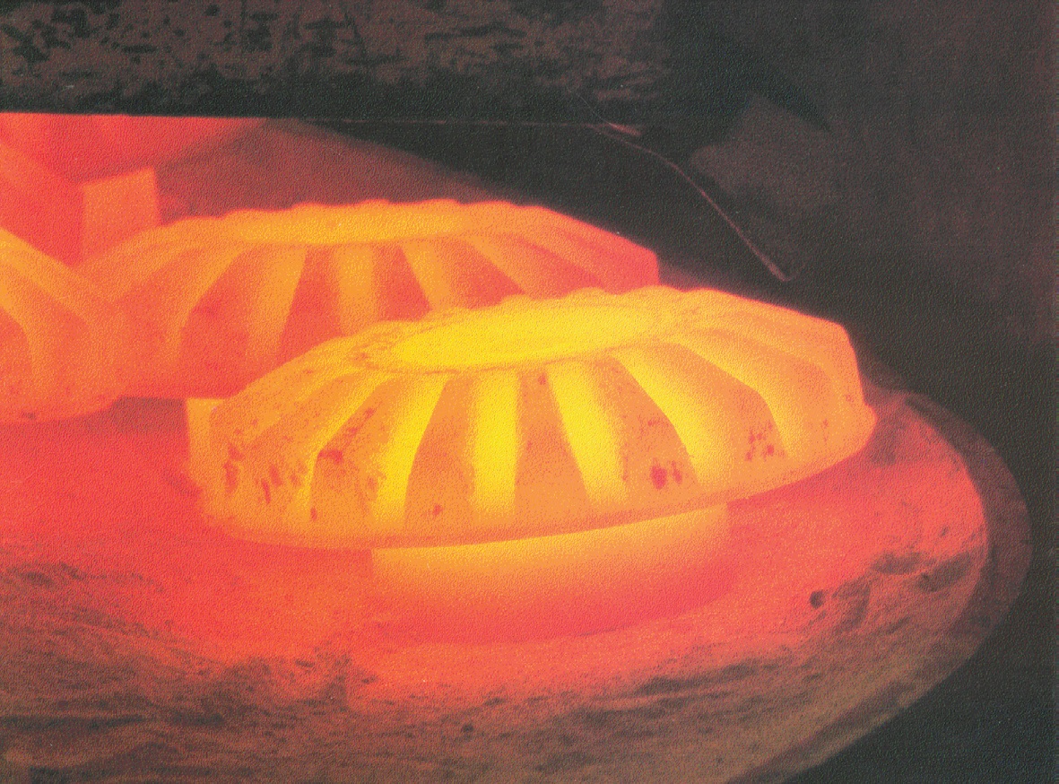 Figure 2. Hot forging of steel is carried out at temperatures between 1,150 C and 1,290 C. A precision bevel gear placed on a cooling table is shown after undergoing hot forging. (Courtesy of Metalworking Consultant Group LLC)
Metal can easily be deformed and made into intricate parts at these high temperatures. But there is a downside to hot forging. Douglas says, “High temperatures can reduce die operating life. In addition, metal oxide (scale) can be generated that can accelerate abrasive wear of the dies. This scale also can become embedded in the end forgings, which leads to rough irregular surfaces and low quality forgings with poorly controlled dimensions.”
A metal-forming lubricant is needed to address the concerns about die wear and prevent sticking and galling of metal from the part being formed to the die. Douglas says, “Under severe operating conditions, an inert material needs to be used that has good thermal characteristics and can minimize heat transfer between the metal part and the die.”
The main lubricant that continues to be used in hot forging is graphite. Douglas comments, “Graphite is the benchmark for the forging industry because it is a very good lubricant that is inert at high temperatures. The presence of graphite enables materials to slide past each other easily under these conditions. Graphite does no harm to either the billet or the die.”
Originally, graphite was dispersed in a mineral oil basestock, but this has proven to be very messy and can result in fires. Over the past 50 years, much of the industry has switched over to graphite dispersions in water. Douglas adds, “Regulatory pressures and the desire by the forging industry for cleaner plants and fewer problems acted as the drivers to facilitate this change.”
Graphite continues to be the best overall lubricant for hot forging, although some suppliers are exploring the use of non-graphite compounds in order to avoid the cleanliness issues of graphite. Douglas indicates that forgers are now manufacturing parts with tighter tolerances, such as the gear forgings shown in Figure 2, using graphite-based lubricants.
COPPER WIRE-DRAWING
Copper wire-drawing is the process used to elongate and reduce the diameter of the metal from a bar or continuously cast stock down to a diameter less than one-hundredth of an inch in diameter. During this process, the diameter of copper wire gradually is decreased from intermediate wire (12 gauge–0.081-inches in diameter) to fine wire (30 gauge–0.0100-inches in diameter) and then potentially to ultra fine wire (44 gauge–0.0020-inches in diameter).
This operation is very difficult and requires the metal-forming fluid to provide a number of important characteristics. David Richards, chief operating officer for RichardsApex Inc. in Philadelphia, says, “The copper wire-drawing compound needs to exhibit excellent lubricity, good cleanliness and low foaming characteristics. In addition, lubricants tend to have sufficient cooling and antioxidant properties.” The latter property is important to help keep the copper metal looking shiny.
For most copper wire-drawing applications, water dilutable fluids are mainly used. Richards indicates that most are either semisynthetic or synthetic fluids. Neat oils are employed mainly in wire-drawing operations using alloys.
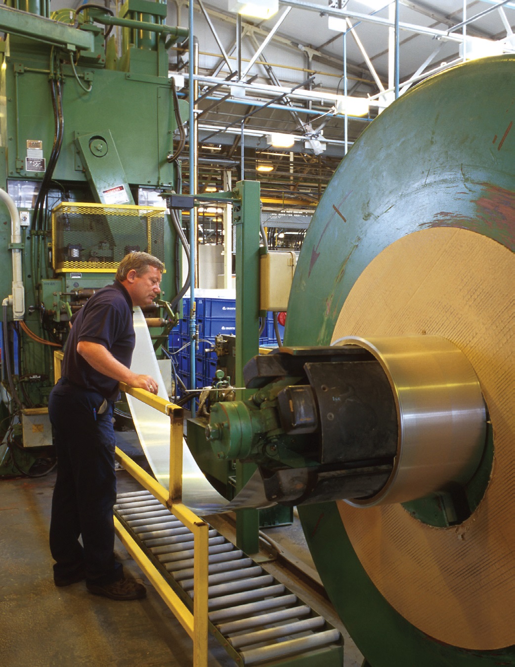
Many factors need to be considered by the metal-forming lubricant manufacturer in order to make a fluid recommendation. Richards explains, “The most obvious questions would be about (1.) the type of wiredrawing machine, (2.) its speeds, (3.) the type of dies used, (4.) the required size of the finished wire and (5.) whether the capstans are submerged or sprayed.” The capstan is a wheel-type device used to control the wire tension as it is pulled through the dies. A typical high-speed, multi-wire, copper machine used in this operation is shown in Figure 3.
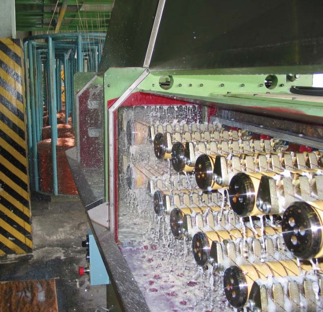 Figure 3. A high-speed, multi-wire, machine used in copper wire-drawing can reduce the diameter of the wire down to as thin as 44 gauge (0.0020-inches). (Courtesy of RichardsApex Inc.)
From a manufacturing standpoint, the wire-reduction sequence and the amount of wire drawn daily through the system need to be evaluated. Fluid pump flow rates feeding the dies and the capacity of the lubricant emulsion tank also need to be examined.
As with most metalworking fluid operations, maintenance is a critical factor in wire-drawing. Richards says, “The existence of a valid maintenance program would tell you how well the system is controlled internally, and tank lifetime expectations need to be considered.” Filtration is an important element of such a program needed to ensure that contaminants do not adversely affect the tight tolerances required in using the wire.
The performance issues facing wire-drawing lubricant manufacturers involve formulating products that exhibit needed lubricity without excessively generating foam while maintaining a sufficiently bright or clean wire. End-users also are looking to increase tank life, which helps reduce disposal costs associated with the manufacturing of copper wire.
FRICTION TESTING
Testing of metal-forming fluids is an important criterion in finding the right product for a specific operation. STLE-member Ted McClure of TribSys LLC in Valparaiso, Ind., says, “In evaluating a sheet metal-forming operation, the key parameters which need to be studied are interactions among the tool, workpiece and the lubricant. These interactions are unusually complex.”
McClure indicates that selection of a test procedure is predicated on what is being studied. Among the possibilities are the lubricants, friction effects and equipment.
McClure says, “A fundamental distinction that people must make when considering which test to use is the difference between bench and simulation testing. Careful attention must be paid to the ways that the specific test can be connected with the industrial process being studied.”
The differences between bench and simulation testing are shown in Figure 4. McClure says, “Simulation tests can be used to study such parameters as process variables, die radii, materials and surfaces, speeds, lubricants, sheet materials and sheet thickness-to-die clearance ratios.” Many simulation tests correlate very well to the actual operation, but McClure indicates that simulation testing only focusing on specific processes has limited flexibility.
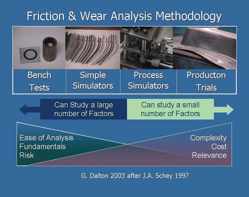 Figure 4. There are distinct differences between using bench and simulation tests to evaluate metal-forming lubricants. Bench tests can provide fundamental data in an easy fashion that may be pertinent to a specific operation. Simulation tests are much more focused on a specific process and cannot be applied to other applications. (Courtesy of TribSys LLC)
He adds, “A simulation study for a hydroforming operation cannot be applied with confidence to any other manufacturing process. The lubricant requirements are completely different as compared to other metal-forming applications.”
An example of a simulation test is the drawbead simulator procedure, which determines the coefficient of friction for forming lubricants on sheet metal. McClure says, “The drawbead test involves pulling a metal strip through a die. It mostly evaluates the lubricant under mixed film and hydrodynamic conditions and does not generate sufficient temperature and pressure to activate most extreme pressure additives.” Lubricants are compared based on their coefficients of friction determined by the test.
Lab bench tests are not used to study process variables but rather focus on fundamental phenomena over the entire spectrum of lubrication regimes. McClure says, “If the user understands where the results from a specific bench test can be applied, there is the potential to achieve good correlation with field trials. The large number of available lab bench tests provides a good deal of flexibility to generate data that might be pertinent to a specific metal-forming operation.”
A lab bench procedure that provides useful information in evaluating metal-forming fluids is the Twist Compression Test. This technique measures the transmitted torque between a rotating annual cylinder (tool) and a lubricated flat-sheet specimen. The lubricant, tool and sheet materials can be varied.
Pressure can be adjusted up to 50,000 psi to best duplicate the actual conditions of the metal-forming process. The coefficient of friction also is calculated in this procedure by determining the ratio of the transmitted torque to applied pressure. A picture of a Twist Compression Tester is shown in Figure 5.
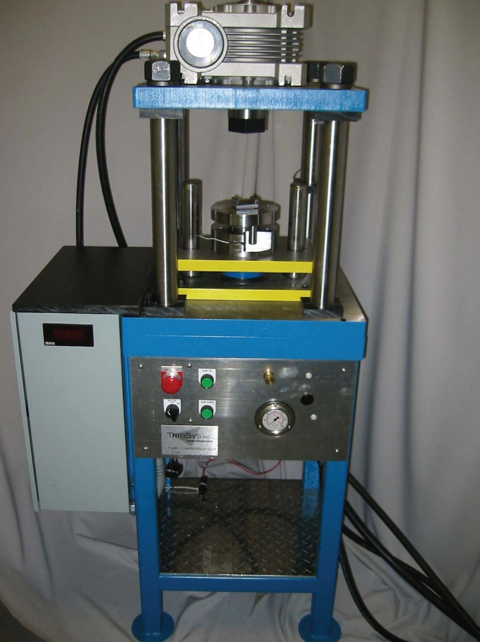 Figure 5. The Twist Compression Tester is a lab bench test that can evaluate lubricant performance over a range of conditions. The transmitted torque between a rotating annual cylinder and a lubricated flat-sheet specimen is measured. (Courtesy of TribSys LLC)
McClure says, “Data can be taken as the test specimen passes through four stages: (1.) initial contact, (2.) primary lubricant mechanism, (3.) lubricant depletion and (4.) lubricant breakdown. The value of the process is that it can evaluate lubricant performance down to lubricant starvation and boundary conditions. At that stage, metal-to-metal contact is obtained as the lubricant is squeezed out from the contact zone.” Lubricants can be compared based on how long they can resist breakdown under severe conditions.
The Twist Compression Test should be done in a comparative fashion using a reference lubricant. McClure believes that this lab bench test offers more flexibility and can correlate with actual field operations if used properly.
Continuing improvements in manufacturing efficiency and in the types of metal alloys used will challenge the metal-forming lubricant suppliers to develop products that meet the diverse needs of these applications. Systematic evaluation of these processes combined with thorough testing will enable the industry to respond with the proper recommendations in the years to come.
REFERENCES
1.
Schey, J. (1983), “Tribology in Metalworking,” American Society of Metals,
134, pp. 1–3.
2.
Tucker, K. (2006), “Metalforming Applications,” in Byers, J.
Metalworking Fluids, Second Edition, STLE and CRC Press/Taylor and Francis, pp. 104–125.
3.
Canter, N. (2007), “Trends in Extreme Pressure Additives,” TLT,
63 (9), pp. 10–18.
 Neil Canter heads his own consulting company, Chemical Solutions, in Willow Grove, Pa. You can reach him at neilcanter@comcast.net
.