Practical oil analysis for impractical scenarios
Jack Poley | TLT On Condition Monitoring January 2009
Hybrid sampling techniques allow you to provide first-rate service in even the most challenging applications.
In November we presented a graphic illustration of suggested relationships and interaction between online, onsite and offsite lube-testing techniques. The composite usage of these techniques was defined as continuous oil analysis.
While this is a very desirable, perhaps even ideal, monitoring concept, it isn’t always practical to employ all three types of monitoring techniques to good effect. Remote, hard-to-access installations often pose sampling problems.
This month we review two specific component and application examples and pose reasonable analytical schemes using a hybrid approach.
EXAMPLE 1: WIND TURBINE FARM
While these machines are proliferating worldwide, they present a significant oil sample challenge. First, there’s no one around to collect a sample on demand, as these machines run unattended. So unless one travels to the wind turbine routinely for other reasons, samples will not be taken regularly.
Second, safely climbing a wind turbine’s pedestal and securing an oil sample is risky business. Attempting to install a long drip leg to allow sampling from the base of the machine safely would likely result in poor samples from stagnant oil and pose a risk of lube loss from a leaking valve or other malfunction.
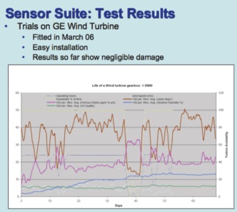
Figure 1. Wind Turbine Maintenance Based on Water Detection
Following are recommended monitoring scenarios:
1. Engage at least two online sensors, one to monitor ferrous wear debris and another to look at oil condition via dielectric monitoring. A third sensor, specific to water detection, also should be considered. Where highly abnormal readings occur, the time and expense of securing and testing an oil sample for clarification becomes perfectly justifiable—someone will need to visit the machine to (at minimum) change the lube out but also to ascertain the reason for the sensor’s alarm. Using only an oil condition sensor will not do, as that type of sensor, while able to suggest problems, cannot isolate the problem’s nature. Thus one could have abnormal wear occurring but mistakenly (wishfully) think an oil change will resolve matters.
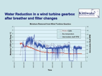
Figure 2. Example of Sensor Suite Tests - Wind Turbine
2. It is appropriate to have maintenance personnel equipped with portable testing kits. Whether they travel to the wind turbine site by land or air, such kits are easily transportable and can reveal additional information. Recommended minimum testing might include:
a. Viscosity (basic vetting)
b. Acid number or other oxidation-indicating tests
c. Semi-quantitative water (contamination).
3. In some cases, especially where ferrous debris is severe, it may be appropriate to perform a field micropatch examination to ascertain the morphology of such particles, a so-called poor man’s ferrography apparatus. This, in turn, could provide sufficient evidence to decide whether mechanical maintenance action beyond lube servicing is required. Or it may trigger a sample routed to an external (offsite) lab, provided turnaround time vs. the need to make a decision is not unreasonably risky.
Bottom Line: Wind turbines are very good examples of machinery that must run unattended for long periods of time. Sensors for wear and contamination detection would seem to be de rigueur in this application, supported by portable (onsite) testing when signaled. This approach is important because routine sampling to perform offsite testing is not usually practical for this application type.
EXAMPLE 2: GAS PIPELINE COMPRESSORS
Like a wind turbine, this machinery often runs unattended. The recommended approach might similarly look something like:
a. Install oil condition sensors in all lube circuits (engine and compressor sumps) at minimum. Consider water sensors, too.
b. In addition, install ferrous debris sensors in gas turbines and four-cycle reciprocating engines. (Two-cycle engines don’t have circulating lube in the cylinder region, therefore ferrous monitoring in the crankshaft sump may not be fruitful enough to justify ferrous debris sensor installation*).
c. In both cases, a portable testing kit comes in handy to qualify lubes for continued use and to correlate with offsite results. Testing can be much the same as for wind turbines except that the base number also might be appropriate for four-cycle engine oils to assess alkaline reserve.
d. There is no reason why offsite testing cannot and should not be performed at regular intervals in routine fashion, as collecting an oil sample is simple in this application.
e. Because two-cycle engines don’t tend to show much iron or have repeatable detectability at tenths of ppm, let alone other wear metals, spectrometric metals analysis might not always spot small but potentially critical movement. Particle counting (minilab onsite or full testing offsite) might be appropriate, in turn supplemented with ferrography for verification and a decision.
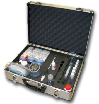
Figure 3. A Typical Portable Test Kit
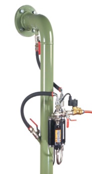
Figure 4. Scrapedown Installation on a MAN 10-Cylinder Marine Engine
*While ferrous debris sensors might not be effective for two-cycle cylinder regions, for the standard notion of monitoring a circulating oil, there are applications that feature individual ferrous debris sensors within each power cylinder. An example is shown in this marine installation involving very large two-cycle engine types.
In this scenario, the scrapedown or excess cylinder lube is gravity-collected and routed to a sensor in every cylinder and ferrous debris is determined. In the process of a trial using this methodology, faulty valve replacement procedure was detected and corrected as an incidental aspect of the installation, clearly showing the efficacy of such an approach.
Bottom Line: Gas pipelines represent collections of unattended machinery, much like wind turbine farms. The difference, however, is that it is relatively easy to collect an oil sample for offline or offsite analysis, so this should be a regular procedure because far more information is then available to make a best decision in the event of abnormal data.
All images courtesy of Kittiwake Developments Ltd.

Jack Poley is managing partner of Condition Monitoring International (CMI), Miami, consultants in fluid analysis. You can reach him at jpoley@conditionmonitoringintl.com. For more information about CMI, visit www.conditionmonitoringintl.com.