Dynamic gas compressors: Selecting the correct lubricant
Mike Johnson, Contributing Editor | TLT Best Practices January 2009
There are two design categories, and you must thoroughly understand the workings of both before making a decision.
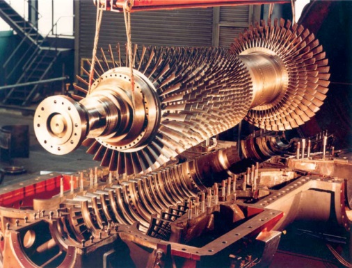
Photo Credit: Siemens Energy
KEY CONCEPTS
•
Common components that require lubrication for a centrifugal compressor include the driver, coupling, gearsets and the bearings supporting the lobe shafts.
•
The design characteristics of axial flow compressors consists of two parts: curved fan blades and a stator.
•
Applying and selecting the appropriate lubricant is essential to long life cycles for all lubricated components.
Compressors are mechanical devices that pressurize and circulate a wide variety of gases (i.e., air, natural gas, oxygen, nitrogen and many types of refrigeration gases) for applications that include providing power for controls, maintaining tension, enabling chemical reactions, moving raw and finished production materials and supplying energy through pipeline transfer of gas to homes scattered throughout industrialized nations.
Without refrigeration compressors, the ability to supply food to entire nations would be lost. These same types of compressors make living in hot, humid climates more tolerable by supplying cool air for homes and offices.
There are many different designs that enable this work to be done. Each design has strengths and weaknesses that make it suitable for its respective application. Compressors may be classified according to the following output or discharge pressures:
•
High pressure—greater than 2,000 kPa, gauge/290 PSIG
•
Intermediate pressure—equal to 800–2,000 kPa, gauge/116–290 PSIG
•
Low pressure—equal to 100-800 kPa, gauge/14.5–116 PSIG
There are two categories of designs: positive displacement and dynamic (continuous flow). Dynamic compressors, such as turbines and axial flow compressors, produce large volumes of relatively low pressure gas.
Last month we discussed the nature of positive displacement compressors and the lubricant selection criteria appropriate for positive displacement designs. This month we address the lubricant selection criteria appropriate for continuous flow or dynamic compressors and their designs.
TYPES AND DESIGNS
There are a variety of compressor types and designs. As shown in Figure 1, there are two categories of designs: centrifugal and axial. Some designs have characteristics of both.
 Figure 1. Compressor Types and Descriptions
CENTRIFUGAL COMPRESSORS
Figure 1. Compressor Types and Descriptions
CENTRIFUGAL COMPRESSORS
Centrifugal compressors are a common design found in industrial process and manufacturing applications. This design uses an impeller to accelerate the gas as it enters the compressor chamber. Some centrifugal compressors incorporate a drive gear coupled to smaller diameter-driven gears coupled to the fan shafts (
see Figure 2). The drive gear accelerates the rotational speeds of the shaft mounted fan, which increases the energy potential of the gas.
 Figure 2. Schematic of a drive gear coupled to smaller diameter-driven gears. (Courtesy of Siemens Energy)
Some centrifugal compressors have fans mounted on a common shaft direct coupled to a drive motor. In this instance, the gas energy potential is increased as the gas passes across each of the side-by-side mounted fans.
In each type, the gas enters the compressor and is accelerated by the impellor or fan blade, turning at very high rotational speed. The high-speed gas is routed from one chamber or stage to the next in sequence where the next impellor adds more energy to the gas stream. After the last compression stage, the gas contacts a diffuser, a funnel-shaped channel at the outlet side of the compressor. As the gas flow enters this volute, the gas flow-speed decreases, and the gas pressure increases as streaming gas accumulates. The kinetic energy from the streaming air is converted into pressure. The behavior of the gas is predictable if the fluid pressure, density and velocity are known.
Centrifugal compressors typically have three lobes or stages, but designs may support between two and six stages. The impellers operate at speeds ranging from a few thousand up to 60,000 rpm. The machines process gas through multiple sequential stages to deliver flows approaching 18,000 cfm. These machines are intended to operate continuously.
The common components for a centrifugal compressor that require a lubricant include the driver (electric motor, process turbine), a coupling, the gearsets and the bearings supporting the lobe shafts.
AXIAL FLOW COMPRESSORS
Axial flow compressors have a design and operation that resembles the jet engine but without the fuel combustion step. Axial flow compressors are used to supply high air flows into gas turbines for aircraft and for some industrial applications. Wind tunnel operators find axial flow compressors to be most useful given their extraordinarily high air flow requirements.
As shown in the opening photo of this article, axial flow designs are characterized by a rotor with a set of curved fanlike blades and a stator. The stator may or may not also have a set of curved blades. The gas enters the compressor body and is spun from the center of the rotor in an outward direction with the rotor blades turning at extremely high speeds.
The gas exits the surface of each fan blade in a radial and tangential direction into the stator blades or housing and is fed into the next stage. The gas is directed into the center of the rotor for the next stage and is pushed along, and the sequence is repeated multiple times. Each set of rotor and stator blades represents a compression stage (
see Figure 3).
 Figure 3. Gas Flow Characteristics for (a) Centrifugal and (b) Axial Flow Compressors (4)
As is the case with the centrifugal compressor, the gas enters a diffuser where the volume of the channel increases with proximity to the discharge port of the compressor. Given gas density, suction pressures and a few other parameters, the process engineer can estimate the output gas volume and pressure for a given rotating shaft speed. Machines capable of delivering 1,000,000 cfm or more have been built.
Axial flow compressor components that required lubrication may include the driver (motor, process turbine), a coupling, seals and shaft bearings. Small machines may employ element bearings, although as the shaft dimensions increase the designer is progressively more likely to employ plain bearings.
DYNAMIC COMPRESSOR LUBRICATION
The lubricant has four key responsibilities in every lubricated component application, including reducing friction and wear, removing heat, removing contaminants and preventing corrosion. There’s a fifth routine lubricant function, providing hydromechanical power transfer, but it does not apply.
Appropriately selected and applied lubrication is essential to long life cycles for all lubricated components. The equipment manufacturer’s conduct through engineering and testing of component requirements and oil supply system flows at specific operating viscosities. These guidelines should be strictly followed.
Lubricant selection for both axial flow and centrifugal compressors follows a similar set of concerns. Dynamic compressors do not require a lubricant within the compression chamber and can consequently deliver oil-free air or gas, which is desirable for many refining and process gas applications requiring large volumes of hot gas to supply production needs. Dynamic compressors employ both element and hydrodynamic journal and thrust bearings in their designs. The choice is heavily influenced by compressor size and application.
Small compressors may be equipped with grease-lubricated element bearings. Element bearings are most effectively protected with the selection of highly work-stable, oxidation-resistant, low-viscosity ball and roller bearing greases. These will be based on low (ISO 32) to medium (ISO100) grade oils, and would be fortified with oxidation and corrosion inhibitors. Grease lubrication of element bearings operating at high rotational shaft speeds requires careful, incremental and continuous supply of lubricant to sustain element function.
Most compressors contain plain (also called journal) bearings for shaft and thrust loading. Again, depending on the size of the machine and the supporting bearings, these may either be continuously flooded or lubricated with an oil disk or floating ring.
Since the lubricants are not exposed to the process gas itself, lubricant selection is based on the needs of the components. Given that gearsets have more severe lubricating requirements than the bearings, lubricant recommendations for bearings are subordinate to the needs of the gearset. The gearset mesh speeds are high enough to allow hydrodynamic (at the gear tooth tip and root contact areas) and elastohydrodynamic (for pitchline contact areas) film conditions. As long as these fat oil films are maintained, the OEM recommendations may include mild antiscuffing (EP) and wear-resistance properties. Traditional EP lubricants that are appropriate for a gear reducer, with low output speeds, are not warranted.
Where only bearings are present (element or journal) inhibited circulating oils (R&O) at 32 cSt are most common. When a speed increaser is used, the viscosity grade may increase to 68 cSt. With a few OEM-specific exceptions, the lubricant type would remain the premium quality inhibited oil.
As is the case with all other gas compression mechanisms, gas pressures and temperatures rise together. High compression ratios produce high gas temperatures, which increases the importance of thermal transfer capacity to cool the rapidly circulated oil.
Lubricant selection for axial flow compressors integrated into gas turbine applications, as shown in Figure 4, will follow the lubricant specifications designed for the gas turbine portion of the application. High-performance synthetic polyalphaolefin ester-based and/or hydrocracked and severely hydrotreated mineral oil-based products are beneficial for limiting heat-induced oil fatigue and thermal degradation.
 Figure 4. Diagram of an Axial Flow Compressor Integrated into a Gas Turbine (6)
SUMMARY
There are two common design directions of dynamic compressor production. Centrifugal compressors are most common for industrial and process applications. These machines provide oil-free air in large quantities and relatively low pressures.
Axial flow machines are common to aviation gas turbines and are used selectively in specialized industrial and process applications. Axial flow machines produce high gas flows.
The lubricant selection for centrifugal and axial flow compressors is relatively simple. The components, high-speed gears and plain bearings, element bearings and seals operate at speeds that create hydrodynamic and elastohydrodynamic conditions, as long as the oil supply is maintained. Accordingly, oil fortification is predominantly for corrosion, heat and oxidation resistance and only to a slight degree for physical surface protection.
REFERENCES
1.
Totten, G.E. and Kazama, T. (2006),
Handbook of Lubrication and Tribology, Vol. 1—Application and Maintenance, Second Edition, Ch. 9., CRC Press (Taylor and Francis Group) and STLE, Park Ridge, Ill.
2.
Bendinelli, P., Camatti, M., Giachi, M., Rossi, E., and Pignone, N. (2001), “Compressor Performance-Dynamic,” Figure 3.1 in
Compressor Handbook, ed., Hanlon, P.C., McGraw-Hill.
3.
Ibid.
4.
Booser, R.E. (1983),
Handbook of Lubrication: Theory and Practice of Tribology, Vol. 1, CRC Press, p. 145.
5.
Wills, J.G. (1980), Lubrication Fundamentals: Compressors, Mobil Corp./Marcel Dekker, p. 386.
6.
Ibid 4, p. 215.
 Mike Johnson, CLS, CMRP, MLT, is the principal consultant for Advanced Machine Reliability Resources, in Franklin, Tenn. You can reach him at mike.johnson@precisionlubrication.com
.