INTRODUCTION: The very-high-temperature reactor (VHTR) is a type of high-temperature reactor (HTR) that can conceptually have an outlet temperature of 1000 °C and coolant gas pressure of up to 9MPa. The very-high-temperature reactor (VHTR), or high-temperature gas-cooled reactor (HTGR), is a Generation IV reactor concept that operates in very high temperature (700-950 oC) and in the presence of helium (He) coolant. It is known that nickel-base superalloys show relatively good resistance against various types of environmental degradation such as oxidation, carburization and decarburization because the protective external oxide prevents the direct interaction of the metal with the helium coolant gas containing the impurities. However, at the high temperatures in HTR, the oxidation resistance of the nickel-base superalloys decreases dramatically because the surface oxide layer no longer acts as an effective barrier against the potentially damaging environment due to the spallation and evaporation of Cr2O3 as well as the high atomic diffusion rate. Inconel 617 and alloy 800HT are the most promising materials for VHTR and HTGR reactor operating temperature.
The objective of this research project is to study the micro/nano scales properties of Alloy 800HT and 617’s surfaces and their oxide layers under high temperature.
HT NANOINDENTATION EXPERIMENTS: Nanoindentation experiments are conducted using a commercial nanoindenter shown in Fig. 1. (TriboIndenter (TI) Premier, Hysitron Inc., Minneapolis, MN). High temperature Berkovich indenter with high temperature stage is used which can measure mechanical and tribological properties up to 800oC. For nanomechanical testing, the alloy samples are polished to roughness (Rq) of 30nm and cleaned using acetone in ultrasonic cleaner. The indentation system also possesses a scanning probe microscopy (SPM) capability and therefore, in-situ surface topography can be measured using a low contact force of 2 μN. It has the capability of supplying gas in the chamber to create required inert environment.
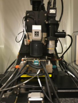
Fig. 1 Nano indenter with HT Stage
To extract mechanical properties such as H and Er from contact area measurements, the same formulation is used which is based on the well-known compliance method for nanoindentation experiments by Oliver and Pharr (1992).1 Mechanical properties are calculated based on the contact area the probe tip makes with the sample under a specific load.
Results and DISCUSSION: Nanoindentation experiments are performed on the samples using the load curve with holding time at peak load that is used to identify the creep behavior of the material and another holding time during unloading is used to study the thermal drift of the samples at different experimental conditions.