An Interferometric Apparatus for the Measurement of Oil Film Thickness in a Journal Bearing
Zafer Dursunkaya, Atae Jafari-Tabrizi
Mechanical Engineering, Middle East Technical University, Ankara, Turkey
INTRODUCTION: Reduction of wear and friction in a journal bearing is of primary importance. Presence of friction and wear not only increases power loss but also reduces component life, resulting in increased maintenance costs. Due to the fact that numerous phenomena are involved in the operation of journal bearings, such as fluid flow, heat transfer, dynamics and solid mechanics; analysis and design is complex. Although numerical and analytical methods are employed, experiments are still needed due to complex and esoteric phenomena such as feeding of lubricating oil and cavitation.
Despite its shortcomings, mobility method, first introduced in [1] is a pioneering and a major contribution to this field, which can also be used in the validation of CFD based techniques. The presence of elastohydrodynamic lubrication and other effects, however, require reliable experimental data for further validation of numerical codes. In [2] a feasibility research of measuring real-time oil film thickness of the journal bearing with optical sensors under variable speed and load is introduced. Results obtained in this work were consistent with mathematical models. In [3] researchers used Eddy current sensors to measure motion of the main journal of a crankshaft. In another study [4] a test rig was constructed, where different conditions acting on the bearing could be simulated and optical sensors were used to measure oil film pressure. Oil film thickness was measured in the guide bearings of a Kaplan hydropower machine [5] with 4 displacement sensors. In none of the above studies optical interferometry was used.
Due to the inherent difficulty in taking measurements in a narrow space—of the order of 50 um —filled with lubricant and rotating at high speeds and subjected to dynamic loading, an interferometer using a fiber optic probe offers a non-intrusive choice for experimental measurements. In this study an interferometric apparatus for the measurement of oil film thickness in a journal bearing is developed and applied inside the main journal bearing of a diesel engine. Accuracy level achieved in measuring relative clearances with an interferometer depends on its operating wavelength, where lower wavelengths result in higher accuracy. The interferometer constructed in the current work operates with a laser source at 1550nm wavelength. Fiber optic components compatible with this wavelength are frequently used in communications technology.
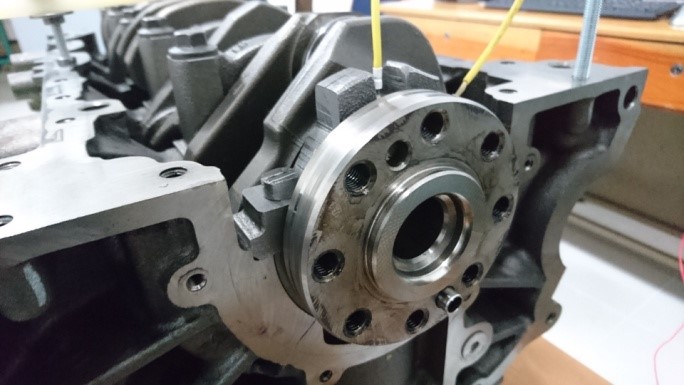
Figure 1 - Optic probes on the bearing hub
METHODOLOGY: A fiber optic interferometer is constructed to measure the variation of lubricating film thickness on one of the main bearings of a 5-cylinder diesel engine. The in-cylinder components are removed and the engine is operated with an electric
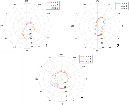
Figure 2 - Journal orbits at (1) low, (2) medium and (3) high speeds
motor. Fiber optic probes are inserted to the bearing through holes drilled in the hub. A total of 4 holes are drilled, and simultaneous measurements are taken from two points of the journal bearing as shown in Figure 1. Interference patterns obtained from two measurement points are detected in photodetectors, and recorded via a data acquisition (DAQ) platform. Signals received by DAQ device are stored in a computer and dynamic displacement of the shaft inside the bearing is calculated through processing of interference data. During data reduction, the data obtained from the two probes are solved simultaneously to resolve the relative motion of the shaft inside the hub. A computer program developed for this purpose is used in data reduction. In addition to the measurements in the bearings, another fiber optic probe is used in the crank bearing of the adjacent cylinder as an encoder, which enables precise measurement of both the rotational speed and the location of the shaft.
RESULTS: Experiments are performed at 3 different speeds, low speed (1.0 rev/s), medium speed (1.6 rev/s) and high speed (2.3 rev/s). From these experiments, three successive cycles of the crankshaft at each speed level are selected to confirm the capability of the algorithm in giving consistent results, validate the measurement technique and to as the effect of the presence of lubricant in the clearance between shaft and journal which reduces the intensity of the laser light. The results obtained from experiments are shown in Figure 2 for three successive rotations of the crankshaft. In all three cases, the shaft followed similar orbits in consecutive rotations.
DISCUSSION: For every different engine speed, shaft follows similar trajectories. In the high speed case, the shaft follows a more circular path, which can be attributed to the effect of a dominant centrifugal force acting on the crankshaft, which is approximately four times larger than gravity. In case of lower speeds, the effect of gravity becomes sensible, forcing the orbits to shift towards earth. Although the presence of the lubricant reduces the intensity of the interference fringes, the effect is not at a level to prevent accurate data acquisition.
REFERENCES: 1. Booker, J. Basic Eng. (1965), 2. Jaloszynski, SAE Technical Paper,(1997), 3. Moreau, J. Eng. Tribology (2002), 4. Ronkainen, Finnish J. Trib. (2009), 5. Simmons, Proc ImechE, Part J: J. Eng. Trib. (2014)