Performance evaluation of thrust foil bearings considering fluid structure interaction
Amirreza Niazmand, Daejong Kim
Mechanical & Aerospace Engineering, University of Texas at Arlington, Arlington, TX
INTRODUCTION: GTFB are a class of compliant bearings which often use air as the working media. These types of oil-free bearings are suitable for small turbomachines operating at high speeds. Typical devices that use GTFBs are blowers, micro-gas turbines and refrigerant cycle compressors. Due to oil free operation, they are environmentally friendly and have many advantages such as low weight, high reliability, low windage losses and corresponding high speed operation. Although, these bearings have numerous advantages, their wide spread use is limited by challenges related to low load capacity during start-stop and requirement of high precision manufacturing. Research is being conducted to address these issues through experimental research or numerical simulations.
Experimental evaluation of GTFB performance is costly and time consuming. Therefore, we can resort to simulations for providing insight into bearing performance.
For simulation of gas foil bearings, most researchers use Reynolds equation to simulate hydrodynamics and for the simulation of structure behavior they use a simplified model to predict the behavior of the compliant surface. Hesmat et al., presented a simplified elastic model for the compliant structure considering the stiffness as functions of material and geometry of the foil[1]. San Andrés et al. developed 1D and 2D finite element model. They considered shell as an anisotropic structure for 2D and a beam-like structure for 1D simulation[2]. Xu et al. simulated air thrust foil bearing to study the sagging effect on the performance of bearings[3]. They modeled top foil by 2D thin plate theory and the bump foils were modeled as spring elements. They found that sagging effects can influence the performance of bearing. Therefore, the thickness of top foil should be selected properly.
METHODS: In this research, an actual bearing geometry consisting of top foil and bump foil without any simplification is used for the prediction of structure behavior. The bearing is modeled as a sequence of pads consisting of top foil resting on bump foil, each with inner radius of 12 mm and outer radius 19 mm. There are six pads which are placed every 60o and the taper ratio is 0.5. The bump foil for each pad consists of multiple strips with pitch of 2mm, width 1.57 mm and height of 0.38 mm. The range of film thickness studied in this research varies from 3 µm to 10 µm. Air is assumed to be the working fluid and the properties are calculated based on real gas model.
The inner and outer boundary conditions are set as ambient pressure in the radial direction while the inlet and outlet of the system are set as periodic boundary in the circumferential direction. Use of constant pressure condition in the circumferential direction may block flow through the film and is not used. To find behavior of fluid film, Compressible Navier Stokes equation is used and finite volume method is used for discretization which is more stable in comparison to FE for simulation of fluids[4]. Fluid structure interaction (FSI) of GTFB is modeled with ANSYS® software. The two-way coupling is utilized in every iteration, for data exchange between two simulations.
RESULTS and DISCUSSION: The simulation results are validated by performing grid independence tests. Further, the final result is compared with experimental results. The simulation results showed good agreement with experimental results.
|
|
|
|
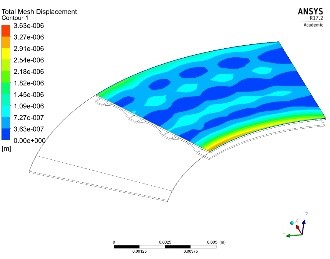
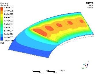
Figure 1: Pressure distribution across the film thickness (right), deflection of top foil (left)
|
The effect of top foil stiffness on the performance of GTFB and pressure distribution over the top foil is investigated in the range of 50k to 150k RPM. Figure 1 shows the pressure distribution over the top foil and the top foil deflection. In comparison to the rigid foil bearings, the load capacity is reduced from 16.7N to 13.2N which indicates a 21 percent difference due to top foil deflection.
The top foil deflection at 50k RPM is not significant. However, as the rotational speed goes up, the deflection of the bearing becomes much more significant and the deflection of top foil can reach to 30 percent of the film thickness in high pressure zones. The deflection of the inner and outer edges of the top foil are high as a consequence of no support at the edges. However, they do not contribute to the load capacity and its deflection can be neglected. This study shows that the effect of top foil deflection on the load capacity is much more than bump foil deflection. To improve the load capacity of a bearing, a thicker top foil may be used or different arrangement of bump foil can be designed to minimize the central deflection of the top foil.
REFRENCES:
[1] H. Heshmat, J. A. Walowit, and O. Pinkus, “Analysis of Gas Lubricated Compliant Thrust Bearings,” J. Lubr. Technol., vol. 105, no. 4, pp. 638–646, Oct. 1983. [2] L. San Andrés and T. H. Kim, “Improvements to the Analysis of Gas Foil Bearings: Integration of Top Foil 1D and 2D Structural Models,” no. 47942. pp. 779–789, 2007. [3] F. Xu, D. Kim, and B. Zamanian Yazdi, “Theoretical Study of Top Foil Sagging Effect on the Performance of Air Thrust Foil Bearing,” no. 49842. p. V07BT31A013, 2016. [4] B. G. Dehkordi, S. Fallah, and A. Niazmand, “Investigation of harmonic instability of laminar fluid flow past 2D rectangular cross sections with 0.5–4 aspect ratios,” Proc. Inst. Mech. Eng. Part C J. Mech. Eng. Sci., vol. 228, no. 5, pp. 828–839, Jun. 2013.