Experimental and numerical analysis of damage of WC composites under impact-sliding

Vincent Fridrici, Marième Fall, Gaëtan Bouvard, Gaylord Guillonneau, Philippe Kapsa

Ecole Centrale de Lyon – Université de Lyon, Laboratoire de Tribologie et Dynamique des Systèmes, Ecully, France

INTRODUCTION: The Fluid Pivot Journal Bearing (FPJB) is a new type tilting pad journal bearing with both hydrodynamics and hydrostatic characteristics. In 1970, L. W. Hollingsworth [1] published his first patent on FPJB which described the basic configuration and the principle operation of this type journal bearing. In 1977, L. W. Hollingsworth and D. V. Nelson [2] summarized large numbers test results on static and dynamic characteristics of FPJB, they also introduced the design and development history of FPJB. From then, FPJB experienced twice improvement. In 1977, L. W. Hollingsworth [3] improved the pad stop of FPJB in his claimed patent, by designing the head of the pad stop to be a convergence shape at the top of it, respectively an arcuate notch on the opposing end of the tilting pad, the tilting pads are better to float freely and better track the shaft that allowing the pad to pivot about their centers. In 2000, A. M. George [4] improved the FPJB by machining a clearance between the outer surface of the pads and the inner surface of the shell, these clearances allow the tilting pads to align themselves with the shaft which changes position due to a variety of dynamic influences, thermal and mechanical distortions. Furthermore, A. V. Harangozo and T. A. Stolarski [5] used an analytical model to predict the unbalance response of a single mass rotor and modeled the FPJB as a two-mass-spring and damper system to study the stability. The results show that with a specific range of frequencies, the FPJB exhibits fine rotor dynamics performance. Many of the configuration design and the test data about FPJB are published, while the analysis on the operation mechanism and the performance of FPJB are inadequate. The present paper will address on this subject.

METHOD: Figure 1 shows the configuration of FPJB, each pad is supported on a self-generated hydrostatic oil film which is created by tapping off a small portion of hydrodynamic oil to pressurize a central cavity on the back of each pad. The pads are geometrically preload     to promote a better hydrodynamic wedge action. By                    assuming that there’s not tilt axially in response to           misalignment, tilting pad in FPJB contains two degrees of freedom, lift and pitch. Under the given condition, shaft and all pads reach to a state of equilibrium which comes from the force and the moment balance of tilting pads. We study this steady state by staring with force balance and moment balance. Furthermore for the lift movement, we should also take flow balance into consideration. Because all pads surrounded by lubricant oil that lift and pitch based on hydrostatic oil film determined by the hydrodynamic pressure distribution. By conducting an   analysis of the range of lifting and pitch of the pads, a computer program based on finite difference method was developed to predict the static characteristics of FPJB including capacity, power loss and oil flow. Then the results of static characteristics are compared with reference [2], also with the results of lobed journal bearing and tilting pad journal bearing by reducing the model of FPJB. Agreement was obtained to prove the valid of the program.


Figure 1 – Abaqus/Explicit model with the ball on flat configuration.

Quadratic elements were used for the flat and tetrahedral elements were used for the ball. The mesh is refined at the contact.

When the ball impacts the sample, it can bounce back or bend the foils that connect the ball holder to the electromagnetic shaker. This should be avoided because it could disrupt the vertical ball displacement.

The ball is modeled with a dynamic high velocity law, known as the Hallomon’s law7. The tungsten carbide samples are defined with an elastic perfectly brittle behavior.

RESULTS and DISCUSSION:  The observation of the wear scars on the ball and the tungsten carbide sample shows that the main wear phenomenon is abrasion. Adhesion also occurs very rapidly and tends to dampen the wear process. Scars are covered with oxides from the ball material. On top of that, some particular wear features are clearly seen at high impact energy8. For the tungsten carbide sample with the lowest fracture toughness, cracks can be observed on the outer part of the contact area.

By comparing the results obtained in numerical modeling and in experimental tests, it was possible to get more knowledge in the sliding distance (about 100 µm for impact energy of 4 mJ), contact area and rebounds, and stresses and strains, which helped us to better understand the tribological behavior of the different couples of materials and analyze the effect of mechanical properties of materials and friction coefficient, in impact-sliding conditions.

The simulation shows that the stress distribution at the contact is linked with fracture occurring on the tungsten carbide with the lowest toughness. Besides, the plastic deformation of the ball plays a role in the contact surface between the two antagonist materials. This influences the size of wear scars on the flat as well as on the ball. Fatigue features observed on the tungsten carbide could be correlated with specific strain localizations (Figure 2).

Concerning quantitative analysis of wear, the model shows that only 10% of the impact energy is converted into friction dissipation. Moreover, wear rate is correlated with the sum of energy dissipated by friction and by plastic deformation, but not with frictional energy.


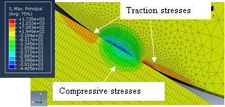
Figure 2 - Abaqus/Explicit stresses (ball on flat configuration).

CONCLUSIONS: This study emphasizes on the damage mechanisms involved in the ball on flat contact during impact-sliding conditions. Stresses and strains involved in the contact during the “impact-sliding” are in great correlation with wear features observed on wear scars. The numerical simulation could help us in explaining the experimental wear features and wear mechanisms.

REFERENCES:  1. Zhang, Mater. Sci. Eng. A (2011), 2. Beste, Int. J. Refract. Met. Hard Mater. (2006), 3. Antonov, Wear (2015), 4. Bailey, Wear (1974), 5. Marou Alzouma, Wear (2016), 6. Messaadi, Wear (2013), 7. Messaadi, Wear (2015), 8. Fall, Wear (2017)