INTRODUCTION: With increasing concerns over the use of fossil fuels and its impact on climate change and global warming, sustainable energy has been gradually gaining more attention. Wind energy has thus seen a steady increase in European investments over the past years and in 2016 accounted for the highest investments in power capacity1. Consequently, it is expected that the wind industry will continue to grow and relied upon heavily to satisfy energy demands and thus the reliability of wind turbines are crucial in keeping wind energy costs low.
Wind turbine gearboxes despite having moderate failure rates, tend to result in the longest downtime2,3. A large proportion of these failures are due to bearing degradation4. It is not surprising as these bearings operate under harsh environment, subjected to high transient loading due to the variability in wind. With better monitoring, understanding of actual loading cases and lubrication within an operational bearing, it will be possible for bearing designers to produce more reliable bearings and turbine operators to better schedule maintenance, preventing long downtimes adding to the reduction of wind energy cost.
Piezoelectric elements bonded onto a component can be used to send and receive ultrasonic signals from an interface of interest such as a contact region or a lubrication interface. Measurements can then be processed to infer information such as lubrication or load. Ultrasonic measurements have been previously applied successfully within the laboratory environment on rolling element bearings for roller load measurements with good accuracy5. In this study, a tapered roller bearing situated within a gearbox of an operational wind turbine located in Barnesmore, Ireland was instrumented using ultrasonic sensors and results obtained were presented. This study aims to demonstrate the capabilities of ultrasound to provide better understanding of actual bearing loads and lubrication during operation.
METHODS: Figure 1 shows the instrumentation carried out on a high-speed shaft gearbox bearing. A tapered roller bearing located on the high-speed shaft within the gearbox was instrumented with ultrasonic sensors. Small piezoceramics were cut into rectangular strips of around 5x2mm, to increase their spatial resolution and bonded onto the outer raceway alongside thermocouples. A small channel parallel to the rolling surface was machined in the outer raceway to accommodate the sensors. Two sensors were installed at the center CH2 and edge CH1 of the maximum loaded region respectively.
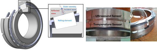
 Figure 1 – Instrumented SKF32222 Tapered Roller Bearing located within an operational wind turbine gearbox
RESULTS: The data in Figure 2A shows the superimposed roller load measurements for 4 complete revolutions for CH1. Measurements shown were for a full bearing complement containing 20 rollers and peaks within the plot correspond to roller passes. Measurements from the same roller were found to be roughly the same, however measurements vary more across the complement. The indication of surface lubrication can be seen in Figure 2B which shows reflection coefficient with time for a dataset captured at low speed (< 20RPM).