Experimental Evaluation of Polymeric Fluid Film Thrust Bearings

Saikrishna Sundararaman

Freudenberg – NOK, Plymouth, MI

INTRODUCTION: Metallic (rolling element and sliding element) thrust bearings are commonly used in automotive and industrial applications to support dynamic loads and relative rotation between components. Depending on the specifics of the application (load, speed, temperature, lubrication, etc.), engineered polymeric bearings can be a feasible alternative to metallic bearings and thrust washers. In addition to providing design flexibility and being axially compact (1.5 mm to 2 mm thick), polymeric bearings are less sensitive to surface finish, surface hardness and angular misalignments, and also provide weight/cost savings and damping characteristics. The choice of base polymer and filler system drives the physical, mechanical and tribological properties of the polymer composite. Although considerable work has been done in understanding tribological properties of polymeric materials 1-4, their use in bearing type applications has been limited. PTFE (Polytetrafluoroethylene) is commonly used as a coating on metallic thrust washers to lower friction and wear 5,6, while PEEK (Polyether ether ketone) and PI (polyimide) polymers are finding applications in tilting pad bearings to replace traditionally used Babbitt type alloys 7-9.

In the current work, two fixed profile polymeric bearing designs developed specifically for automotive transmission applications are evaluated for frictional performance using a modified test method that maintains ‘close to isothermal’ conditions at the interface. The Stribeck curves for these tests indicate that these designs operate as fluid film bearings and exhibit friction coefficients in the same order of magnitude as rolling element bearings. Results also indicate that that isothermal Stribeck curves generated at multiple load / speed combinations tend to collapse to one curve which is indicative of the performance of the specific design.

METHODS: Thrust bearings in two patent pending designs (LevitorqTM D4 and LevitorqTM D7) were manufactured using Torlon 4275 polyamide-imide engineering polymer. Torlon 4275 is an injection moldable polymer with desirable mechanical and tribological properties and exhibits good chemical compatibility and a glass transition (Tg) temperature in excess of 280°C. The thrust bearings have an inner diameter of 56.25 mm, an outer diameter of 77.95 mm,  a thickness of 1.75 mm and have twelve load supporting pads with 0.3 mm deep grooves in between the pads to allow for flow of lubricant (Dex VI transmission fluid). The difference between the two designs is in the cross-section of the grooves. While the groove profile is constant for the LevitorqTM D4 design, the LevitorqTM D7 has a tapering groove with diminishing cross-sectional area along the radial direction.

The performance of these designs was evaluated using a specialized thrust bearing test stand that was designed, developed and built in-house at Freudenberg-NOK. The test stand is capable of applying an axial load of up to ~22kN (5,000 lbs.) and a has maximum rotational speed of 10,000 rpm.  Lubricant can be supplied at a maximum flow rate of ~11 liters/minute (3 gallons per minute) / pressure of 2 MPa (300 psi) and up to a maximum temperature of 150°C (~300°F). The data acquisition system records temperatures, fluid pressure, fluid flow rate, axial thrust force, rotational speed, wear to the bearing and frictional torque. Fluid flow can be arranged either from the ID to the OD of the thrust bearing or vice versa. Tests can be set-up such that a constant fluid temperature is maintained either at lubricant inlet or at the interface (measured 1 mm below the running surface at four locations 90 degrees apart) by varying fluid inlet temperature based on the friction condition at the contact.

The evaluations on the LevitorqTM D4 and LevitorqTM D7 designs were conducted by maintaining a constant user specified temperature close to the interface. The lubricating fluid was directed from the ID to the OD of the bearing at ~ 3.8 lpm (1 GPM). Thrust loads of 2.2kN (500 lbs) and 4.4 kN (1000 lbs) were used for these tests and rotational speed was varied from 500 rpm to 10,000 rpm in increments of 500 rpm. Each load/speed combination was run for 35 minutes to ensure that ‘close to isothermal’ conditions were reached and maintained at the interface. The counter surface used for the tests had an Ra of 0.2 µm and a Rockwell hardness of ~ HRC 20.

RESULTS AND DISCUSSION: Figure 1 plot coefficient of friction (COF) as a function of duty parameter, G (G = hW/P, where h is dynamic viscosity, W is the angular velocity and P is the average pressure on the pad) for LevitorqTM D4 and LevitorqTM D7 designs at thrust forces of 2.2kN (500 lbs) / 4.4 kN (1000 lbs) and temperatures of 180°F / 220°F on a log-log scale.


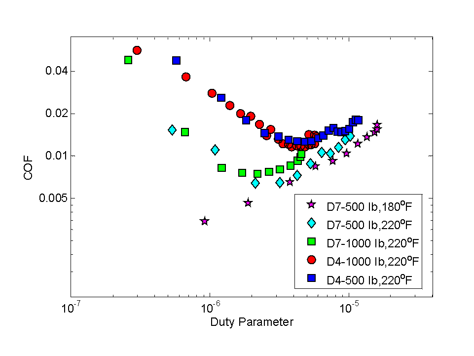
Figure 1 – Friction coefficient vs Duty Parameter for D4 and D7 designs under ‘close to isothermal’ interface temperature conditions

The following conclusions can be deduced from Figure 1:

  1. Design affects COF: The difference between friction coefficients for the LevitorqTM D4 and the D7 designs can been seen in Figure 1. At 220°F, both designs show a decrease in COF with increasing duty parameter, until it reaches a minimum value after which there is an increase in COF. A noticeable difference for minimum COF and the onset of full film lubrication is evident indicating that design influences friction behavior.
  2. Temperature influences lubrication regime: The COF for LevitorqTM D7 at 180°F shows a monotonically increasing trend indicating that the bearing operates in the full film lubrication regime at this temperature. This was also evident from the lack of wear marks or polishing on the surface of the bearing after this test (not shown).
  3. Effect of Load: For both the LevitorqTM D4 and the D7 designs, increasing load from 500 lbs to 1000 lbs (with interface temperature at 220°F) shifts the Stribeck curve to the left. The COF, however  is dependent on the Stribeck parameter and does not change significantly from the COF values for the 500 lb Stribeck curves. Additional data needs to be considered  and reviewed to better understand this behavior.

REFERENCES: 1. Shooter, Proc. Phys. Soc. (1952), 2. Golchin,  J Eng. Tribology.(2013), 3.Nilsson, Friction. (2013), 4. Quadrini, eXPRESS Polymer Letters. (2007), 5. Jackson, Tribology Transactions. (2003), 6. Nunez, International Compressor

Engineering Conference.(2010) , 7. Zhou, Lubricants. (2015), 8. Wodtke, Tribologia. (2016), 9. McCarthy, Lubrication Science. (2009)