Influence of mesh and geometrical parameters on the performance of a wet clutch disc

by means of CFD simulations

Youssef Bouayach1,2, Jean Bouyer 1, Michel Fillon1

1Institut Pprime, CNRS – University of Poitiers – ISAE-ENSMA, Futuroscope Chasseneuil, France

2RENK France, Saint-Ouen-l'Aumône, France

INTRODUCTION: Automatic transmissions use wet clutches to connect or to disconnect different rotating parts of gearboxes in order to change the speed ratio. During an engagement, it exists a slip velocity between the friction disk and the separator disk which produces frictional overheating. The system is continually supplied with an Automatic Transmission Fluid (ATF) to lubricate the components and to evacuate heat. When the clutch is opened, the presence of ATF between disks implies a viscous torque, i.e. energy losses. The challenge is to reduce them and to improve the heat dissipation thanks to a better understanding of the clutch behavior.

Recent studies like that of Iqbal et al. [1] and Takagi et al. [2] suggest a two-phase flow to estimate the drag torque for a non-grooved clutch. Initially, the mass flow is sufficient and the drag torque is proportional to the rotating velocity. Then, the drag torque decreases with an increase of speed because of the presence of air between the disks. Aphale et al. [3] presented in 2006 a parametric study of torque in an open clutch. Parameters were rotation, number of grooves and clearance. They found that drag torque decreases with an increase in clearance or an increase of the number of grooves.

In the present study, the authors developed a CFD model by considering a single phase, in order to carry out a parametric study. Straight grooves have been chosen for all cases and variable parameters were the clearance between disks, the depth, the width and the angle of the grooves. During an engagement, the clearance between the disks decreases implying a shearing torque increase, and consequently an increase of the temperature. As mentioned by Yang et al [4], it is important to evacuate the heat produced at this particular moment as efficiently as possible.


METHODS:  A numerical model has been developed on ANSYS CFX. Numerical simulations showed the important influence of the mesh dimensions on the results. In fact, due to the presence of the grooves that leads to geometrical discontinuities, a variable step mesh has been necessary to obtain a stable convergence. Furthermore, an optimized distribution of the mesh on the domain allowed a reduced computation time and permitted to obtain accurate results. To understand the influence of each geometrical parameter, only one parameter varied for each study: the groove width from 1 to 6 mm, the groove depth from 50 to 500 µm and the inclination of the groove from -60° to +60°. Moreover, the rotating speed was comprised between 250 and 4 000 rpm. The clearance between fixed and rotating disks also varied from 10 to 600 µm.


RESULTS & DISCUSSIONS

Figure 1 presents the effect of a clearance decrease for a rotating velocity of 3 000 rpm. When the clearance is less than 100 µm, the torque is very high and increases very quickly with a clearance decrease. Over 100 µm, the torque decreases weakly with the increase in clearance and remains almost constant after 300 µm.

Furthermore, simulations show that more than 98% of the fluid flows through grooves for clearances less than 100 µm. Grooves will thus play an important role in terms of cooling in this situation. Figure 2 shows the calculated oil flow rate as a function of groove depth at a rotational speed of 3,000 rpm. In this case, the contact surface of disks remains constant. The flow is proportional to the

groove depth. One can note that in real applications, the flow is fixed by the limit of the pump. The idea is to optimize the geometry of the friction disk to obtain an oil flow rate during an engagement less than or equal to the flow rate of the pump; otherwise, the cooling will be less efficient. The most critical state is the case with the lower clearance and the highest rotating velocity. For the lower clearance (10 µm), the flow rate and the torque decrease with the velocity. When the groove width is increased from 3 to 6 mm, the flow rate is increased by 121%, whereas the torque is decreased by 12%. The inclination of the groove has only a weak effect on the torque: when varying the inclination from 10° to 60°, the torque is reduced by 6% while the flow rate is increased by 142%.


N = 3000 rpm


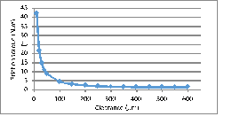
Figure 1 – Friction torque versus clearance between disks.

N = 3000 rpm


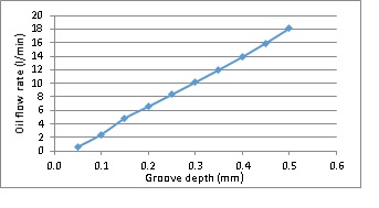
Figure 2 – Total oil low rate versus groove depth.


CONCLUSION:

The parametric study gives a better understanding of the effect of each parameter. It presents a tool that allows optimizing the flow on a wet clutch in order to cool efficiently the system.


REFERENCES: 

[1]. Iqbal S., Al-Bender F., Pluymers B. and Desmet W., “Mathematical Model and Experimental Evaluation of Drag Torque in Disengaged Wet Clutches”. Hindawi, Volume 2013, Article ID 206539.

[2]. Takagi Y., Nakata H., Okano Y., Miyagawa M. and Katayama N.“Effect of Two-phase Flow on Drag Torque in a Wet Clutch”. Journ. of Adv. Research in Physics 2, 021108, 2011.

[3]. Aphale C. R., Cho J., Schultz W. W., Ceccio S. L., Yoshioka T., Hiraki H., “Modeling and Parametric Study of Torque in Open Clutch Plates”. Journ. of Trib., Vol. 128, 422-430, 2006.

[4]. Yang L., Ma B., Ahmadian M., Li H.  and Vick B., “Pressure Distribution of Multidisc Clutch Suffering Frictionally Induced thermal load”. Trib. Trans., 59:6, 983-992, 2016.