INTRODUCTION: Pure rolling contacts in a cylindrical roller bearing are ideal and perfect, but actually contacts of a cage with rollers and other components shouldn’t be ignored. The contacts will inevitability lead to sliding friction.1 Most frictions wears in a bearing are led by sliding movements, including circumferential sliding/rolling and axial reciprocating sliding. And a tilting angle can be used to describe the severity of misalignment.2,3 In addition, edge stress in the line contact of a partial crowning roller will be quickly increased by tilt, which necessarily lead to surface distress but contributes to asperities flattening, even with a large slide-roll ratio2. Otherwise, under some extreme work conditions, especially without satisfied oil supply, early failures of a rolling element momentarily occur.4 In general, a spiral groove seldom appears as a type of abrasive of bearings, but it is quite common during grinding machining process of cylindrical roller bearings.5 In this work, with multi-factors for extreme conditions, experimental investigation on wear mechanism and helical groove formation of rolling pairs would be conducted in both macro and micro scale. Also the effects of radial sliding on axial groove formation would be got.
METHODS: Test rig of roller bearings with sliding contacts can be seen in Figure 1. VFD of low-speed motorized spindle (4) was used to get different ring speeds n, given at the values of 300 r/min, 500 r/min, 700 r/min and 900 r/min. Radial load F (500 N) can be got with a device (8) and measured with a sensor (7). Roller specimens with partial crowning were used in this test. Because for the radial clearances (< 10 µm) of the support bearings (5), a small tilting angle α (0.001 rad) of a roller specimen (3) can be set with a small variation of the platform height (9), while the height of inner ring (6) was invariant. At axial direction, reciprocating sliding displacements would be led by elastic deformations of the spring coupling (2), shaft clearances of support bearings and the fit allowance (≈ 0.5 mm) between the support bearings (5) and the loading device (8). At circular direction, circumferential slip ratio s can be got with different couples of ring speed and ring speed, i.e. the values of 0, 0.2, 0.4, 0.6 and 0.8. The equation of slip ratio2 is,  , where
  ,
,  ,
,  is the
diameter of a roller, is the pitch diameter of a rolling element,
  is the ratio of to . In fact, speed value w( w=2πn/60 ) of inner race (6) on the test rig is the difference-value of inner ring speed
  and revolution speed of roller
 , i.e.
  .
.
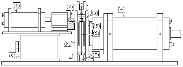
Figure 1 - Test rig of roller pairs6:(1) motorized spindle with high-speed (2) spring coupling (3) roller specimen (4) spindle with low-speed motorized (5) spring bearings 6000z (6) bearing inner race NU1019 (7) loading sensor (8) Loading device (9) lifting platform.
RESULTS: In this work, sliding frictions led by cage movements were concerned. Under an oil-lack condition, an interesting helical groove is led by roller tilt and sliding contacts (at axial direction